RIP
I've been silently working on and off on this, and I now have a question. For the hammer sensors, I am almost settled to the design mentioned above, which looks like this:
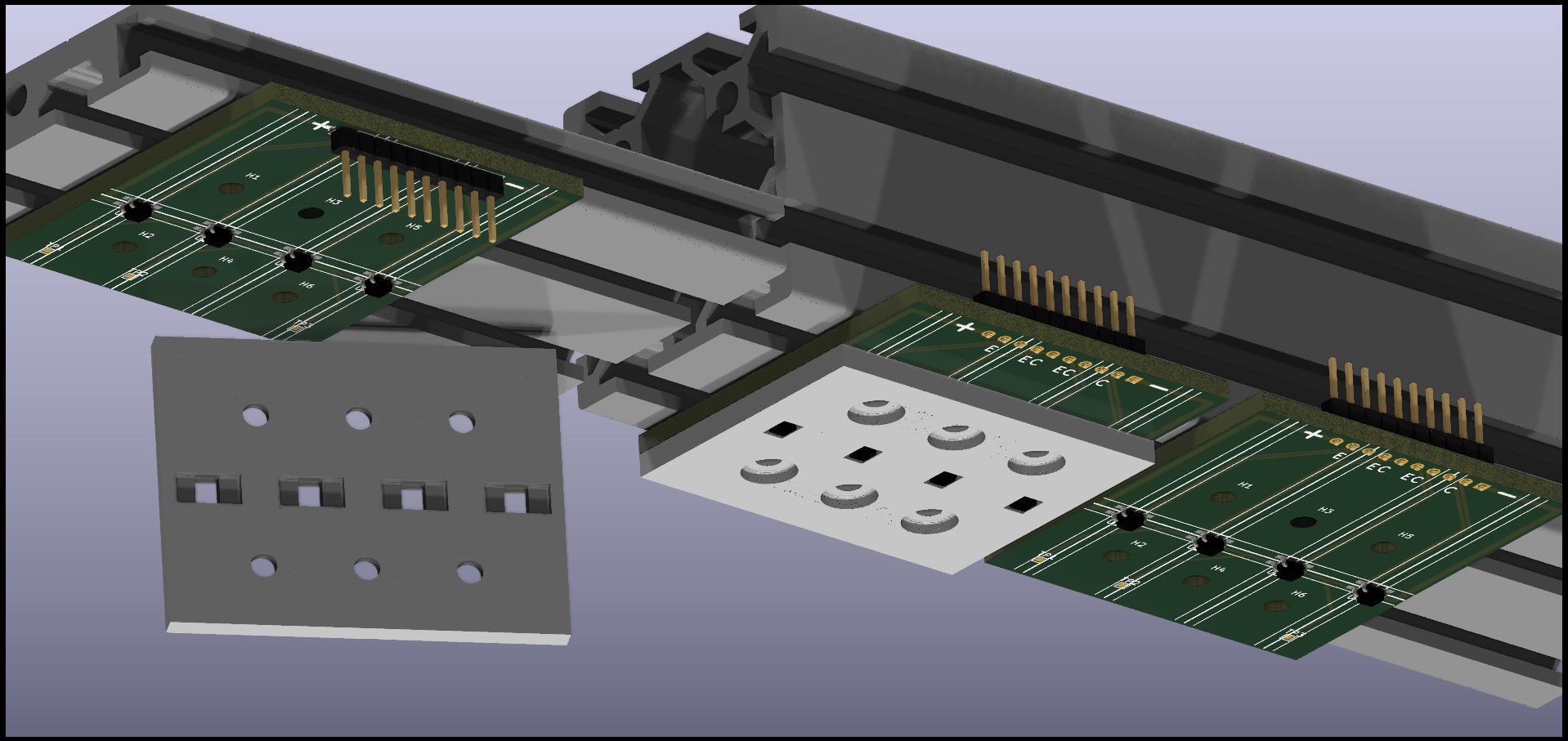
This works mechanically good, based on my cardboard models. In case it's not clear, you are looking at the sensors (those four black things on the green PCB) from the bottom. The hammers will hit them.
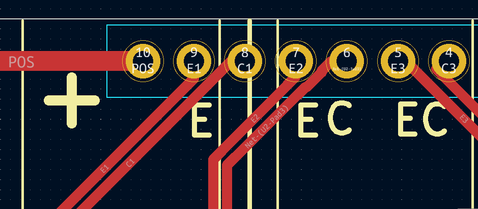
Now, for the damper sensors, the best approach would be to use a similar (note 1) board. The best way to mount that would be to use an extrusion like https://us.misumi-ec.com/vona2/detail/110302261730/?ProductCode=HFSQN4-1030-1382 to mount them under the keys, on the back where the back action is (or would be if it's removed). The problem is that header to attach the jumper connectors. It can't be in that direction, since that goes below the Keybed. One option could be to use angled connectors, but that has other complications that I don't want to get into, so my preference would be to simply mount the connector on the other side of the board, namely the same as where the sensors are.
The problem with that is that the soldering would be on the wrong side of the PCB, so the question for people who know more about that than I is if I could use the same mounting hole as a via, or if I need a separate via for that. As always, other solutions/ideas are well accepted and sought after.
(note1): since there is an extremely high cost for setup, having 176/4 + spare boards that are all identical would be most ideal, rather than 88/4 boards of one kind and 88/4 boards of another, which would cost more than double than having everything identical (I have already studied how to make sure that I can use boards with 4 sensors even though none of my hammer sections is made of a multiple of four hammers -- obviously there will be unused/unconnected sensors, the problem was that the spare one might be in the way).
I am not sure if the volume price would apply for an assembly of the jumper of two sides, but I hope so.