Skip to content

Another DIY hybrid

sawyer bergeron

RIP the code in question: https://github.com/szbergeron/hybrid_piano/blob/main/sampler/src/main.cpp#L557 and https://github.com/szbergeron/hybrid_piano/blob/main/sampler/src/main.cpp#L758

It's interspersed with logic to optimally saturate both ADCs on the Teensy since not all of the analog pins are muxed to both of them. I was going to see if I can cram coroutines in there (or manually lower some async logic) to continue doing note processing while waiting on each sample, just to keep the ADCs "fed" with requests a bit better. The CPU is waiting around doing a whole lot of nothing most of the time anyway, so any time the ADCs are waiting on the CPU is time arguably wasted. If I'm still seeing note variation from lack of sample density, I have the board set up so I can add additional teensys to break up the daisy chains down to as little as one board each.


vagfilm

@sawyer bergeron Just to clarify, because I am bit lost (as usual… 😀) : you are only measuring key travel, correct? No hammer detection… And where are you placing the sensors? On the keys or in the keybed? With an external magnet or metal piece?

Many moons ago I toyed with a fixed hall sensor below the keys and a small magnet on the underside of the key, and gave up because I had a lot of crosstalk from the neighboring keys. This means that I chose the wrong design or the wrong sensor 😀...


sawyer bergeron

vagfilm I'm measuring hammers, sensors are going to be mounted on a rail above them, with magnets on the shanks. I did a test with a Lego model while I was getting my salvage action, and did find there to be some crosstalk, but I can do a relatively simple transformation to "de-convolve" the gaussian to reduce it from the 10 parts in a hundred down to likely sub-0.5 compared to the direct signal from the matching hammer. Basically, take the measured value from neighboring keys (to some reasonable kernel size) and subtract some offset as calculated by some mapping function. You can do that once for a significant reduction, out to n times (with scaled down contributions each time) in a long tail of diminishing returns. The (observed, but not scientifically measured) low noise I'm seeing from the sensor is really exciting to me, since it means even if I have to do some corrections I'm at least not going to be forced into wasting a bunch of measurements just filtering out noise.

I'm definitely winging this a bit, I've never been much of a person for the controlled rigor of science (let alone writing it all down…) but so far everything has been quite straightforward and had pretty obvious choices just from looking at the outputs.


vagfilm

Thanks. I assumed you were measuring key travel and not hammers because you mentioned something like using early movement to assign faster sampling. Somehow that sounded more appropriate to keys than to hammers. Very nice project…


sawyer bergeron

Finally got my action in, and realized I was naively optimistic in my hope that the hammers would be evenly spaced save for the gaps between each bank of hammers. Having separate sensor boards from controller boards was probably the way to go all along. Initial tests (with legos, some tape, and a spare set of hands to hold things in place) indicate that I way overspec'd my software, and piano hammers don't move as fast as I assumed they could in the worst case scenario. That does give me some extra headroom for adding an extra control board with some slide potentiometers on it as a midi control surface though 😃


sawyer bergeron

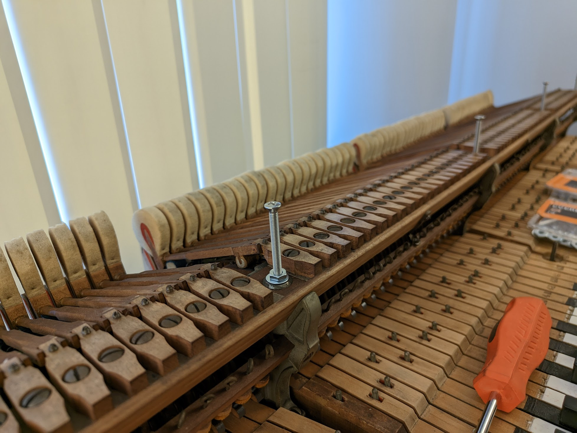
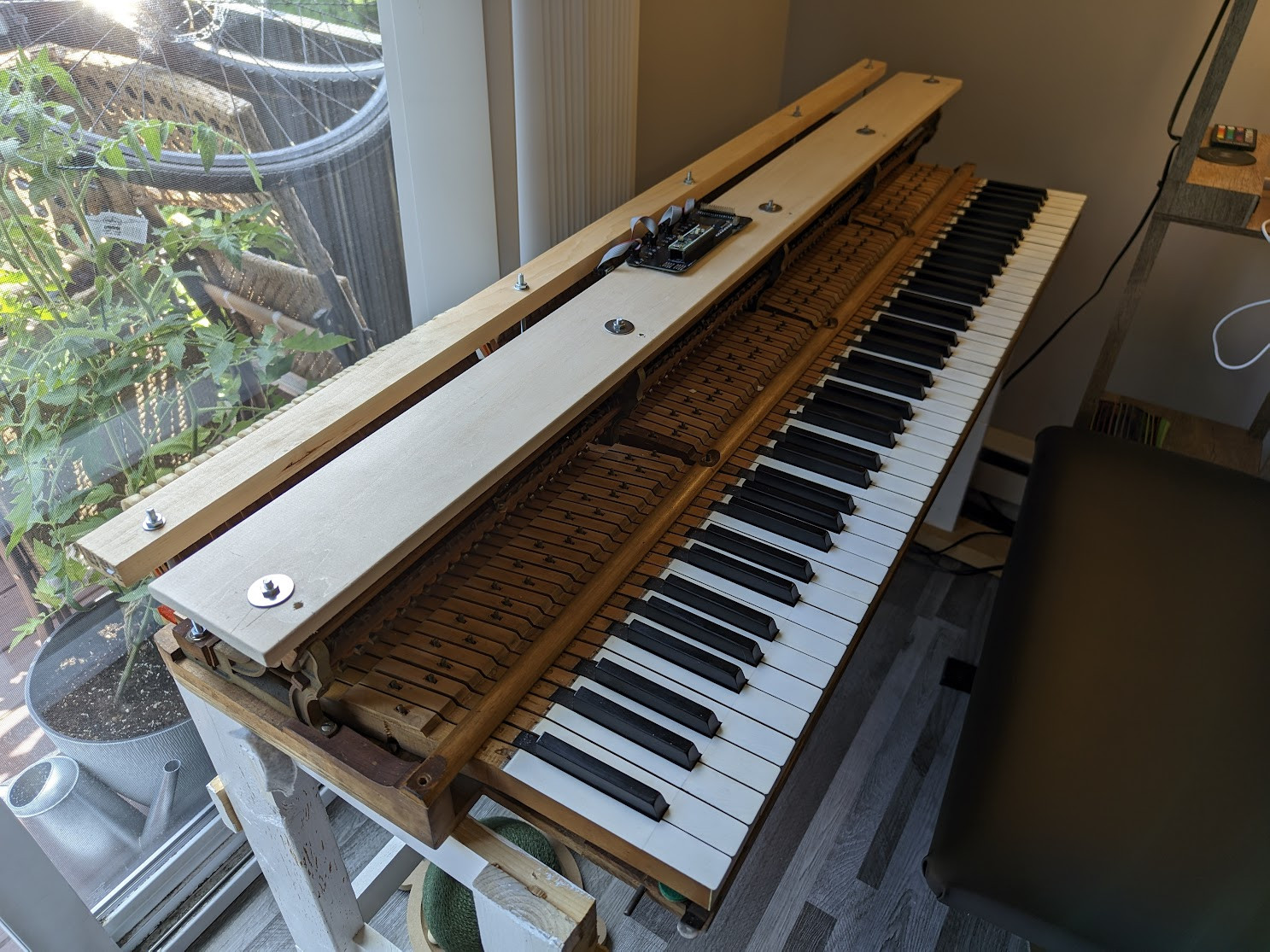
Going to try a bit of an experiment for mounting the sensor rail: I've found threaded rods that match the threading for the screws that hold the hammer rail to the top action, which are the same as the ones that hold the whippen rail to the brackets. Hopefully, I can attach the striker rail to the rear rail (with some rubber washers for damping) and the sensor rail to the ones extending from the hammer rail. If having the striker rail coupled even that much to the top action causes too much vibration then I might have to redesign my cabinet a bit, but I'm cautiously optimistic that it'll work

I figure the more tightly I can couple the sensor rail to the hammer rail at least, the better my readings will be even in the presence of vibration (it would require rotational vibration to see any significant disruption, not just translational)


sawyer bergeron

Some initial eyeballing of my measurements tells me that I've struck gold with the mounting arrangement. I'm not seeing any of the wobble that @gzpiano mentioned with the extrusion based mounting. Getting the extra supports along the length I'm sure is most of it, since it constrains any oscillations to the 4th harmonic of the bar, which seems to damp out basically immediately (with it being wood, and not something that rings in those harmonics like aluminum would)

I do very badly need to regulate the action though. I have the striker rail height set to catch the hammers at the correct angle going by the string wear marks, but still a full half of the jacks aren't coming off of the knuckles so those hammers stay bouncing at the top of travel. I'm debating if I can do a good enough job regulating by myself, or if it would be worth it to hire a pro and hopefully be "done with it".

Re: hall effect sensors: that part itself works amazingly. The hammers in the real action are spaced out more than my model was, so I see even less cross-talk. The bus architecture also seems fine, even putting analog signals over a few feet of ribbon cable, 1 microsecond of switching delay before doing reads seems to be plenty for everything to stabilize (haven't tried pushing it down more than that yet).

Next steps may not be mechanical at all, since aside from a bunch of stupidly annoying manual soldering (why did I have to choose SPST switches the size of coarse salt grains? why didn't I pay for some robot in china to just do that for me?), I think the remaining MVP problems can be completely solved in software.


gzpiano

Looks promising!


RIP

sawyer bergeron I'm debating if I can do a good enough job regulating by myself, or if it would be worth it to hire a pro and hopefully be "done with it".

In the spirit of DIY, it'd be worth it. In the spirit of getting it done sooner rather than later, hire a pro, if you know a good one already (if you have to fish one out, you may not save much time if at all).
If you do it yourself, I strongly recommend this book

http://www.pianosinsideout.com/

In any case, looking forward to seeing where this brings you!


ambrozy

in old actions regulation is more about understanding the issues and fixing them or working around them, blindly setting every adjustment point as it “should be” usually doesn't work.


sawyer bergeron

ambrozy do you think it would be worth going over the action and doing a full felt replacement and such, or would I be better served just regulating with what it has on it? Prior owner was a music teacher, so it's pretty worn but is at least regulated within probably the past 20 years. I've swapped the front/balance rail punchings since the old ones had been eaten by time, but the whole top action is how I found it at the moment minus some minor cleaning


ambrozy

As I said, first you need to assess the situation, find where the major problems are. replacing all bushings, centerpins and rollers? that's not happening if you have no tools and no experience. Maybe start with simple thing, check if front rail pins and balance rail pins are not corroded, front and balance bushings in keys are not worn out completely, how much play is in there, key balance holes are not too tight or too lose, measure downweight and upweight of all keys, calculate balance weight and friction from this (try to determine if you have static friction issues because if there is high static friction somewhere, measurements will be wrong), check how much rollers are worn out.

If you show some photos of those parts I may be able to say something more


sawyer bergeron

ambrozy front rail/balance rail pins aren't corroded, but have worn through the plating over time. The bushings, though, have a good bit of play that I was hoping to fix. The balance holes on the keys themselves have little/no play and are in good condition. Very little static friction from the bottom action, though I'll definitely need to add some graphite/lithium in some places in the top action while I regulate it, as it's very hard to play PP and PPP on this at the moment--the jacks don't want to come off of the knuckle without some force. The knuckles don't seem particularly worn away, but do seem to have deformed a bit over time where the jack/whippen support it. I can add some photos down the line, as at the moment I'm mostly busy getting the electronics/software sorted and "boxed up".

@gzpiano for calibration, I know you ended up using a crane to measure nonlinearity, did you try doing any profiles of just letting the hammer "fall" under its own weight before going to using a dedicated rig? I figure I can grab a bunch of samples as it falls and transform those measurements knowing acceleration due to gravity, but if there are pitfalls to that approach I'd love to hear em before I force myself to do the annoying math/input filtering involved in grabbing that data 🙂 Turns out magnetic fields are the "complicated" kind of non-linear so I'm doing my best to just have the calibration sequence fit a polynomial to the observed flux_density(distance) curve.


sawyer bergeron

It "works" at the moment, but I have some unevenness to sort out and the velocity mapping definitely needs some tuning. Next step is figuring out mounts for the electronics and then a whole f*ck ton of soldering. I also still have a lot of headroom for doing extra computation while waiting for the ADCs to do their conversions, wondering what else I can cram onto here to actually use the resources the teensy gives me.

https://photos.app.goo.gl/f22W1ug1ZN7oeikH7


ambrozy

To minimize the bump you need to:

1. Set the jack position as far backward as possible for it to work properly, (too far backward will work for pianissimo playing but may slip from under the knuckle at forte blows)

2. Set the drop as late as possible, when drop is set later than highest point of letoff, there is no bump (and so no problem with extreme pianissimo), it can't be set that way in acoustic piano because there is aftertouch and that causes repetition lever to rise above the letoff point and so hammer to rise and block to the strings, but maybe you could take this into consideration in software, you can think about it

3. Lubrication, fine teflon powder works best, but it doesn't stick very well to the knuckles (actually it doesn't stick at all lol) but with repeated applications some of it stays deeper in the surface and stays a little longer, wet lubricants are little risky and can make a mess, I personally don't use them.

And of course you need first to set other things close to where they should be, letoff, repetition spring (at least to be strong enough to hold the hammer for now), repetition lever height (can't set it properly if spring is too weak) and aftertouch. Try to set one sample note and play with settings, you may get some understanding this way, do not try to set all the keys to some standard that you find in some book or somewhere without any thought because it will fail most likely as this is not a new action and standard settings will not work well.


gzpiano

sawyer bergeron

Nice to see the project progressing!

stem piano applies an exponential curve fit. I put calibration in run-time, and it estimates parameters automatically when play piano.

To see the code algorithms, start at component link below and then follow link for "StemPianoIPS2 Firmware" about 3/4 way down the component file. The source code is calibration_position.cpp.

(I didn't link directly to the .cpp file because "DIY" repo links may change in future as migrates to stem piano repos):

https://github.com/stem-piano/stem-piano-g-main/blob/main/documentation/component_manual.md


sawyer bergeron

Calibration for the sensors works pretty well, though getting "perfectly" even key velocity measurements might take an additional measurement step. So far, calibration is just "lift each hammer all the way up, and then let it fall", which takes ~1-2 minutes for 32 keys. Hard to tell how much unevenness is just because the entire thing is bouncing all over the place on the current stand.

https://youtu.be/siqSPc1QJVQ


sawyer bergeron

Returning to this after quite a while, some updates:

The original architecture was a cool proof of concept for the idea itself, but I think needs a rev2 at least, and I'm pretty much completely redoing the software.

A bit part of the problem has been trying to fit "everything" onto the one teensy. The muxed ADCs on it are, combined, plenty fast and have a perfectly sufficient SNR when doing smoothing/resampling. The problem is that 512k of TCM, even with the additional 512k of non-TCM, is just not enough to store all of the samples at once that I need in order to do correlative calibration. Even at 8 bytes per sample (16 bit absolute value, 48 bit timestamp) I would only be able to hold a couple hundred samples per key.

On the other hand, the teensy is very capable as a "smart" ADC, timestamper, and data acquisition unit. There's a 480mbit USB HS 2.0 port right there, and I've set up flatbuffers via COBS encoding over the serial-style link I get over that. With "empty" message insertion, I should be able to avoid even the worst-case 1ms of latency from USB polling.

All of this means that the sound generator is going to need to be part of the system, and run some software. On the other hand, this means I can write the smarts in an environment with virtual memory, a normal allocator, multiple cores, 64 bit native word sizes, and can consume many whole megabytes of memory. This also means I'll be integrating a bar-style LCD panel for controlling it with a custom UI (probably written in Dioxus, I've been meaning to learn that) and however much number gathering/number crunching I want.

So, far from dead, but this gives me a chance to also re-spin the boards with component selection that isn't as fiddly to hand solder (those tiny analog switches were the bane of my existence), boards that fit into cheaper 10x10cm layouts, and sensor boards that have a more reasonable way to securely mount them. From an EE perspective this has been plenty robust, and I probably went a bit overkill on protecting signal integrity, so I can likely make things a bit more compact this time around.

Very excited to pick this back up and hopefully make a final push to get it done.


« Previous Page Next Page »