Skip to content

piano midi controller diy

CyberGene

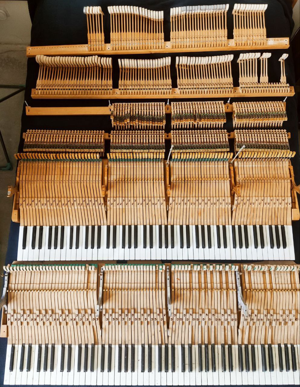
scherbakov.​al This is a keyboard mechanism from a Red October grand piano.

That’s interesting. For the last few days Valentina Lisitsa has been teasing about a mysterious grand piano she obtained recently and it appears to be a Red October grand. From the comments she made, there’s a speculation that it’s the grand piano Horowitz played when he recorded a recital at the Moscow Conservatory in 1986. I even read about Red October and its history because I heard the name for the first time. Seems it’s the legacy of a German piano builder who settled in Russia and made some fine pianos.

https://m.youtube.com/watch?v=QgBpOi_OEqs

https://vplate.ru/pianino/krasnyj-oktyabr/


RIP

scherbakov.​al This blew my mind,

Yeah, that's pretty common. Before embarking into this project myself, I too thought the pianos actions were all interchangeable. They are not! Even from the same manufacturer, even from the exact same model, there are some adjustments that are not drop-in interchangeable but needs adjustment. Yamaha is an exception, they have very tight tolerance in their process that you can almost replace the whole action from one piano to another (of the same model!!) with very minimal adjustment.

but nevertheless I managed to assemble Frankenshain)

Alright, that explains some of the things that I saw. Congratulations of making it work, that's not an easy feat!

scherbakov.​al This is a keyboard mechanism from a Red October grand piano.
CyberGene Like, why it has waterfall keys?

Still I have never seen a piano with waterfall keytops and even a google search for images of R.O. pianos did not turn anything like that. Quite interesting....

CyberGene For the last few days Valentina Lisitsa has been teasing about a mysterious grand piano she obtained recently

I saw that but I have not watched the videos just yet...


scherbakov.​al

Some selection process.. what can be collected from what..


scherbakov.​al

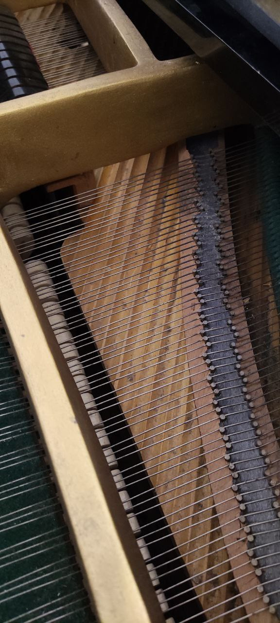
At work, in the corner of the hall, a large old Red October grand piano with an unusual soundboard shape was discovered


scherbakov.​al

CyberGene Seems it’s the legacy of a German piano builder who settled in Russia and made some fine pianos.

Once upon a time they were quite good. But later the pianos were produced in such huge quantities...simply millions, at that time in a collapsing country, and the quality was sometimes like that of a cheap cabinet with strings

RIP They are not! Even from the same manufacturer, even from the exact same model, there are some adjustments that are not drop-in interchangeable but needs adjustment

absolutely right!


scherbakov.​al

Melinoe There is only a general review video and it does not explain anything. It is located in the 17th message from December 19 in this branch.


Melinoe

scherbakov.​al Oh that is exactly what I was looking for. It seems to work quite well.


Melinoe

scherbakov.​al

"learning how Git"

Did you ever end up starting a git for the project?

Edit: You mean like right above your post? I'm dumb.


scherbakov.​al

Melinoe "learning how Git"

Did you ever end up starting a git for the project?

Please clarify the question. I didn't really understand because of the translation.


scherbakov.​al

Now we plan to add automatic switching on of the power supply and sensors using a relay when the microcontroller is turned on. So as not to pull the power plug in/out of the socket every time. There will also be a migration to the stm32h723 board with a display. It has a slightly higher clock frequency (550 MHz). I have already learned how to connect a display and display information on it. An encoder will also be added to change some settings. So that you don’t have to reflash the microcontroller from the computer every time to change some internal number.

https://youtube.com/shorts/lFRHzwrIzIs?si=jW3MvkXeYpCW29Z0


scherbakov.​al

So, some changes:

- moving to the STM32H723 board with a display. The project was rebuilt in CubeIde

- added a display to display some information

- added a relay. Now there is no need to pull out/plug the plug into the outlet

- an encoder has been added. You can adjust some parameters and turn off the piano

- added saving of parameters in non-volatile memory

- added standby mode. When you turn on the piano, it goes to sleep. It is activated by a button on the controller board. In case of inactivity, it turns off after 10 minutes. It can also be disabled using an encoder. Now there is no need to disconnect the USB cable

- an error has been identified and fixed due to which every 8th key sometimes played a slow speed

- keyboard scanning has been slightly accelerated. Now the keyboard scanning speed is more than 300 kHz (~310)

- the light indicates that the speed is exceeded

https://youtu.be/30M5jO6VT-U

https://github.com/ScherbakovAl/midi_keyboard_h723


n-player

VSThost I like these projects.

Starting from tiny ones that just add a LED strip to show the keyboard splits, from big projects such as the Netherblade.

Great video with Eric Netherland, thanks for linking it. It is more than just a keytar on a screen. There are some interesting software features. I don't think there is any tactile feel on the screen so it seems one would need to look at the screen 100% of the time when playing.

I have to say that these new-age MIDI controllers knock down limits but seem to struggle to sound "musical", to my ears.

My favourite controllers are the Hakken Continuum & the Linnstrument.

  • I enjoyed the Hakken's sponge feel
  • I enjoyed Linnstrument's remapping of notes. And the square keys that are adaptive & colorful.

Some of these fancy MIDI controllers seem to promote un-natural hand movements and tension so I would be worried about hand injury.

Some of the footpedals, mice gizmos, and breath controllers get around these issues. The breath controllers for winds seem awesome.

https://www.hakenaudio.com/slim-continuums
https://www.rogerlinndesign.com/linnstrument


scherbakov.​al

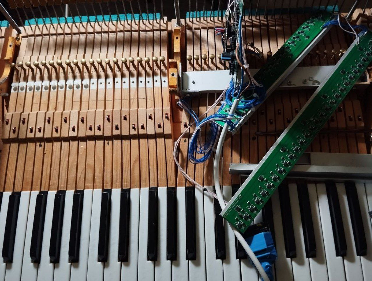
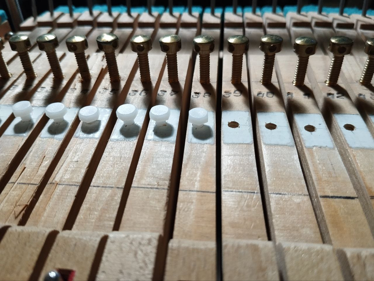
So, it's been a while since I last updated my theme. Overall, the optical system has performed very well for me. I used it to prepare programs for speaking with school students at competitions and exams, and after studying at home, I didn't experience any difficulties or problems when moving to a live piano.I also used Pianoteq at home, and it was surprising how the sensors above the hammers behaved quite evenly and predictably despite not having any adjustable resistors or a calibration system in the circuit. While there may be some unevenness in the speeds between notes if you look closely, it wasn't critical. However, the sensors for the damper system didn't work as expected, and in the beginning, I even painted the areas under the sensors with white paint, but it didn't improve the situation.. Then I added plastic adjusting screws, the heads of which I coated with a patina so that they would not be detected by optical sensors (polyethylene was found to be transparent to the sensors).

In the process of adjusting these screws using a micrometer, it became clear that this did not significantly improve the situation. There is a wide range of parameters in the damping system. Now, I am considering the need to add an automatic calibration system. This would require a revision and extensive redesign of the electronic circuit. I would need to go through the PCB manufacturing process again. However, I am determined to do so. I hope to have a perfectly functioning design in the summer that will meet my expectations in all respects!

I also found another piano mechanic (now there are three in my small apartment). This one has been in use for a long time and needs some felt parts to be replaced and retuning parameters. Unlike previous keyboards, it has all the keys and mechanisms intact. And it's the same brand as my other piano, so all the board sizes are the same.

Another improvement I'd like to make in the future is to have a more attractive and user-friendly screen menu. It's not essential, but I think it would be a nice addition.

Also, it's absolutely necessary to change the aluminum-polyurethane stop rail for a wooden one with a rubber stop for the hammers. A neighbor from the apartment next door complained about the noise of tapping behind the wall, so I think that would solve the problem.

That's all for now. Let's start the new year with fresh plans!

Happy holidays to all!


scherbakov.​al

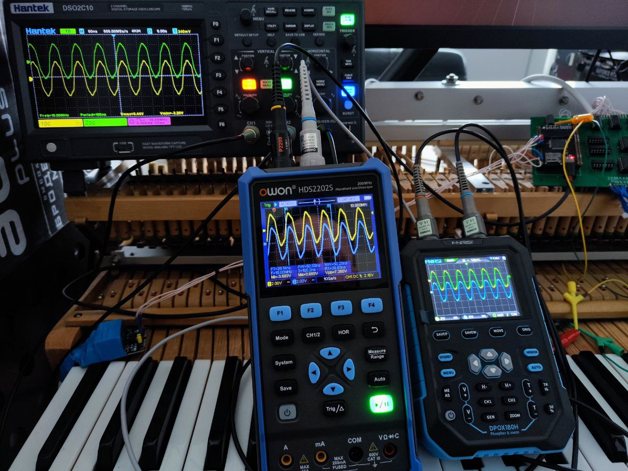
I was attacked by oscilloscope fetishism!

@DavisB opened my eyes to the HC238 analog multiplexer. When I started doing this project, I was experimenting with some kind of (I don't remember which) analog multiplexer. And it seemed extremely slow. It is possible that I was doing something wrong, measuring or controlling it incorrectly, but since then I have given up the opportunity to consider multiplexers. I still remember their slowness. And then I switched to researching the operation of shift registers. But this damn thing (HC238) works extremely fast! So yesterday, a couple of multiplexers appeared, let's get started!


DavisB

scherbakov.​al
As far as I can tell, "the slowness" - if any - really comes from capacitance of phototransistors.
Most HC series ICs are fast by themselves (for our requirements anyway!).

CD4051 1-to-8 analog muxes work without any issue whatsoever switching at 160kHz (meaning each sensor 20kHz)
The HC238 also work well, but in the circuits I drew previously the adjacent sensor readings influence each other somewhat (which might be ok for slit sensors, but not for the analog ones). So those hc238 circuits are incomplete and need improvements that fully address the capacitance and properties of phototransistors.

One of the big goals with using HC238 was to cut down power consumption below 500mA, such that it can directly be powered by USB.

I was also thinking that it might be possible (?) to have all leds be constantly on and still be under 500mA budget.
Regular phototransistors has forward voltage of ~ 1.2V, meaning you could one LED current limiting resistor per two sensors in series.
If we're aiming for around 9-10mA for each led, that would give us ((3.3v-(1.2v * 2))/100ohm) * 44pairs = ~ 396mA. (5V->3.3V via LDO)
Few mA for MCU and ~ 30mA (3.3/10kohm)*88 pullups/pulldowns - and even the basic-always-on CD4051 muxing version might work just from 500mA USB?


scherbakov.​al

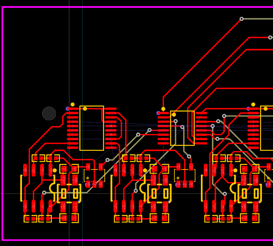
Time has shown that the ability to calibrate sensors is an important and necessary function. It turned out that there are digital resistors. (Mcp4351). I learned about them recently. I decided to try to add them to the existing circuit. I assume that adding these digital resistors would add 3 more (maybe 4) communication lines from the central controller to the boards with sensors. They are controlled via SPI. There are options for i2c control, there is an option with memory and without. I learned to control resistors, it is not difficult. I sketched out a circuit and sat down to redo the board layout.

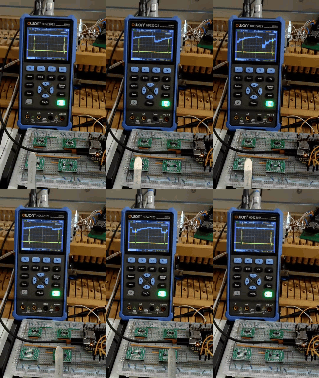
But it turned out that some stm32 can contain a comparator. For some reason, I did not pay attention to this before. I searched and found stm32g473, which have 7 comparators and 7 DACs on board. It seems that the DACs can be used to set the comparator response point programmatically. Now I'm waiting for several stm32g473 for training and testing. I'm also interested in the analog multiplexer. But not ch238(It turned out that it connects one channel into many, but SN74LV4051). I tested its operation at a speed of 1 MHz. (Switching channels with a frequency of 8 MHz and running the entire circle for ~ 1us) and the result does not satisfy me yet.

At such a speed, the channels influence each other too much. I will come up with some other connection scheme and test. This is exactly the scanning speed I would like to achieve (it would be 3 times faster than the option with shift registers). If it worked out, it would be nice.

@DavisB - what if you switch to USB 3? It supports power supply up to 3 amperes.


« Previous Page Next Page »