Skip to content

piano midi controller diy

scherbakov.​al

Now we plan to add automatic switching on of the power supply and sensors using a relay when the microcontroller is turned on. So as not to pull the power plug in/out of the socket every time. There will also be a migration to the stm32h723 board with a display. It has a slightly higher clock frequency (550 MHz). I have already learned how to connect a display and display information on it. An encoder will also be added to change some settings. So that you don’t have to reflash the microcontroller from the computer every time to change some internal number.

https://youtube.com/shorts/lFRHzwrIzIs?si=jW3MvkXeYpCW29Z0


scherbakov.​al

So, some changes:

- moving to the STM32H723 board with a display. The project was rebuilt in CubeIde

- added a display to display some information

- added a relay. Now there is no need to pull out/plug the plug into the outlet

- an encoder has been added. You can adjust some parameters and turn off the piano

- added saving of parameters in non-volatile memory

- added standby mode. When you turn on the piano, it goes to sleep. It is activated by a button on the controller board. In case of inactivity, it turns off after 10 minutes. It can also be disabled using an encoder. Now there is no need to disconnect the USB cable

- an error has been identified and fixed due to which every 8th key sometimes played a slow speed

- keyboard scanning has been slightly accelerated. Now the keyboard scanning speed is more than 300 kHz (~310)

- the light indicates that the speed is exceeded

https://youtu.be/30M5jO6VT-U

https://github.com/ScherbakovAl/midi_keyboard_h723


n-player

VSThost I like these projects.

Starting from tiny ones that just add a LED strip to show the keyboard splits, from big projects such as the Netherblade.

Great video with Eric Netherland, thanks for linking it. It is more than just a keytar on a screen. There are some interesting software features. I don't think there is any tactile feel on the screen so it seems one would need to look at the screen 100% of the time when playing.

I have to say that these new-age MIDI controllers knock down limits but seem to struggle to sound "musical", to my ears.

My favourite controllers are the Hakken Continuum & the Linnstrument.

  • I enjoyed the Hakken's sponge feel
  • I enjoyed Linnstrument's remapping of notes. And the square keys that are adaptive & colorful.

Some of these fancy MIDI controllers seem to promote un-natural hand movements and tension so I would be worried about hand injury.

Some of the footpedals, mice gizmos, and breath controllers get around these issues. The breath controllers for winds seem awesome.

https://www.hakenaudio.com/slim-continuums
https://www.rogerlinndesign.com/linnstrument


scherbakov.​al

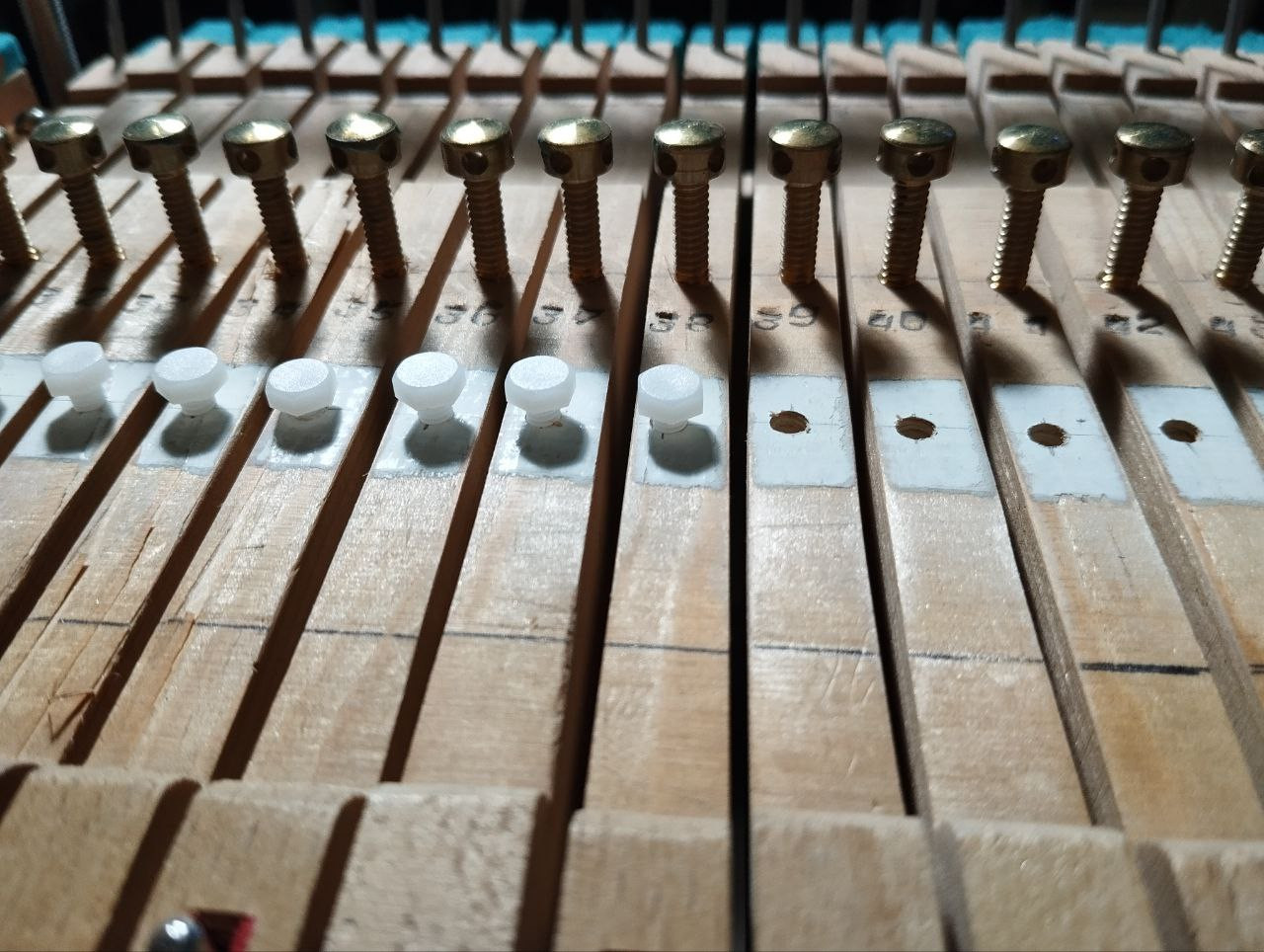
So, it's been a while since I last updated my theme. Overall, the optical system has performed very well for me. I used it to prepare programs for speaking with school students at competitions and exams, and after studying at home, I didn't experience any difficulties or problems when moving to a live piano.I also used Pianoteq at home, and it was surprising how the sensors above the hammers behaved quite evenly and predictably despite not having any adjustable resistors or a calibration system in the circuit. While there may be some unevenness in the speeds between notes if you look closely, it wasn't critical. However, the sensors for the damper system didn't work as expected, and in the beginning, I even painted the areas under the sensors with white paint, but it didn't improve the situation.. Then I added plastic adjusting screws, the heads of which I coated with a patina so that they would not be detected by optical sensors (polyethylene was found to be transparent to the sensors).

In the process of adjusting these screws using a micrometer, it became clear that this did not significantly improve the situation. There is a wide range of parameters in the damping system. Now, I am considering the need to add an automatic calibration system. This would require a revision and extensive redesign of the electronic circuit. I would need to go through the PCB manufacturing process again. However, I am determined to do so. I hope to have a perfectly functioning design in the summer that will meet my expectations in all respects!

I also found another piano mechanic (now there are three in my small apartment). This one has been in use for a long time and needs some felt parts to be replaced and retuning parameters. Unlike previous keyboards, it has all the keys and mechanisms intact. And it's the same brand as my other piano, so all the board sizes are the same.

Another improvement I'd like to make in the future is to have a more attractive and user-friendly screen menu. It's not essential, but I think it would be a nice addition.

Also, it's absolutely necessary to change the aluminum-polyurethane stop rail for a wooden one with a rubber stop for the hammers. A neighbor from the apartment next door complained about the noise of tapping behind the wall, so I think that would solve the problem.

That's all for now. Let's start the new year with fresh plans!

Happy holidays to all!


scherbakov.​al

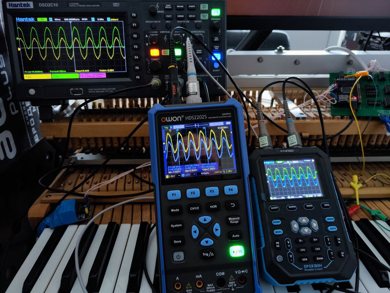
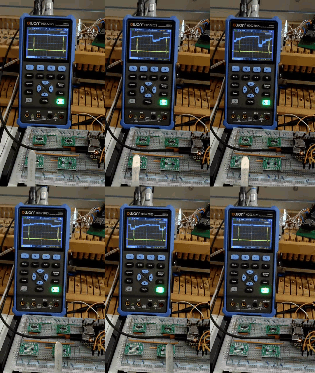
I was attacked by oscilloscope fetishism!

@DavisB opened my eyes to the HC238 analog multiplexer. When I started doing this project, I was experimenting with some kind of (I don't remember which) analog multiplexer. And it seemed extremely slow. It is possible that I was doing something wrong, measuring or controlling it incorrectly, but since then I have given up the opportunity to consider multiplexers. I still remember their slowness. And then I switched to researching the operation of shift registers. But this damn thing (HC238) works extremely fast! So yesterday, a couple of multiplexers appeared, let's get started!


DavisB

scherbakov.​al
As far as I can tell, "the slowness" - if any - really comes from capacitance of phototransistors.
Most HC series ICs are fast by themselves (for our requirements anyway!).

CD4051 1-to-8 analog muxes work without any issue whatsoever switching at 160kHz (meaning each sensor 20kHz)
The HC238 also work well, but in the circuits I drew previously the adjacent sensor readings influence each other somewhat (which might be ok for slit sensors, but not for the analog ones). So those hc238 circuits are incomplete and need improvements that fully address the capacitance and properties of phototransistors.

One of the big goals with using HC238 was to cut down power consumption below 500mA, such that it can directly be powered by USB.

I was also thinking that it might be possible (?) to have all leds be constantly on and still be under 500mA budget.
Regular phototransistors has forward voltage of ~ 1.2V, meaning you could one LED current limiting resistor per two sensors in series.
If we're aiming for around 9-10mA for each led, that would give us ((3.3v-(1.2v * 2))/100ohm) * 44pairs = ~ 396mA. (5V->3.3V via LDO)
Few mA for MCU and ~ 30mA (3.3/10kohm)*88 pullups/pulldowns - and even the basic-always-on CD4051 muxing version might work just from 500mA USB?


scherbakov.​al

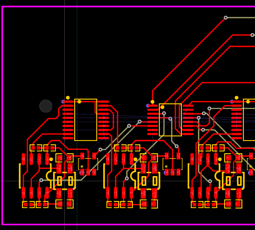
Time has shown that the ability to calibrate sensors is an important and necessary function. It turned out that there are digital resistors. (Mcp4351). I learned about them recently. I decided to try to add them to the existing circuit. I assume that adding these digital resistors would add 3 more (maybe 4) communication lines from the central controller to the boards with sensors. They are controlled via SPI. There are options for i2c control, there is an option with memory and without. I learned to control resistors, it is not difficult. I sketched out a circuit and sat down to redo the board layout.

But it turned out that some stm32 can contain a comparator. For some reason, I did not pay attention to this before. I searched and found stm32g473, which have 7 comparators and 7 DACs on board. It seems that the DACs can be used to set the comparator response point programmatically. Now I'm waiting for several stm32g473 for training and testing. I'm also interested in the analog multiplexer. But not ch238(It turned out that it connects one channel into many, but SN74LV4051). I tested its operation at a speed of 1 MHz. (Switching channels with a frequency of 8 MHz and running the entire circle for ~ 1us) and the result does not satisfy me yet.

At such a speed, the channels influence each other too much. I will come up with some other connection scheme and test. This is exactly the scanning speed I would like to achieve (it would be 3 times faster than the option with shift registers). If it worked out, it would be nice.

@DavisB - what if you switch to USB 3? It supports power supply up to 3 amperes.


scherbakov.​al

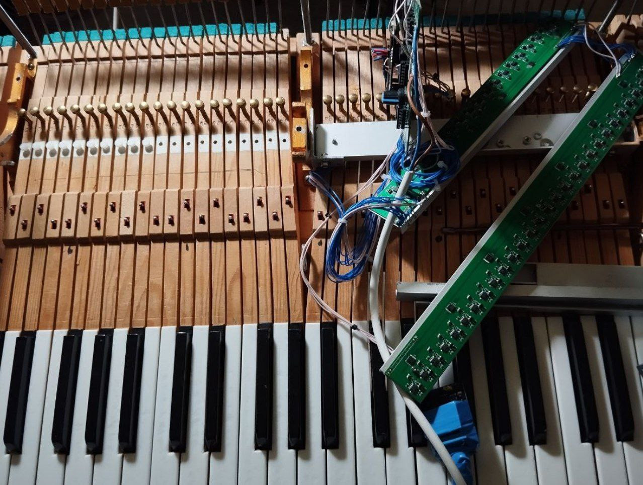
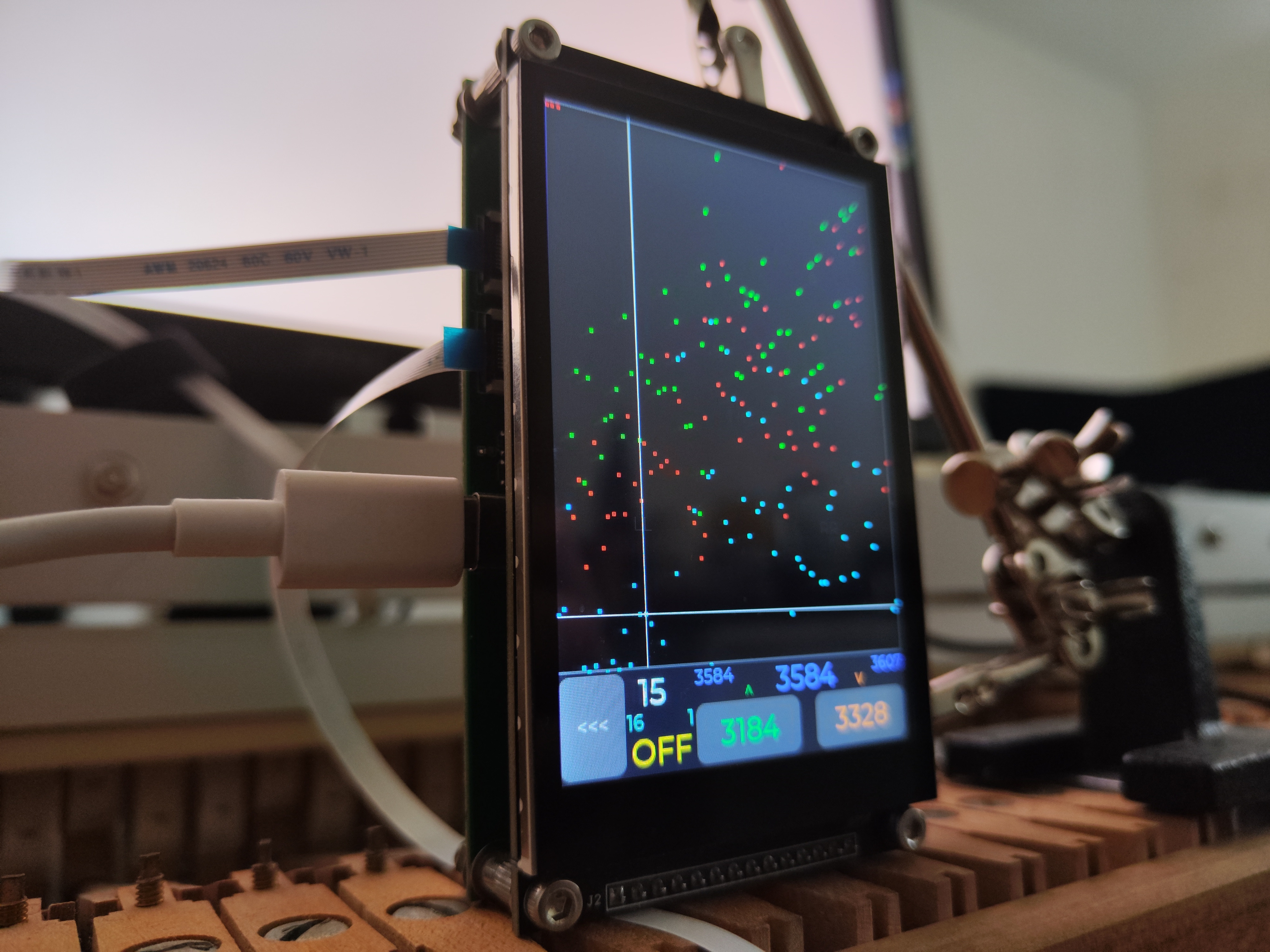
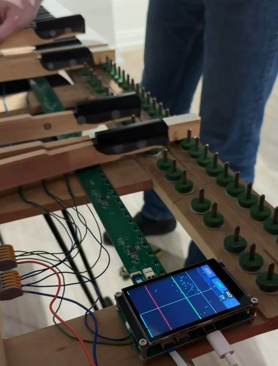
The homemade MIDI piano controller has been updated. The controller is now more compact, has a color touchscreen, connects to the boards using a pair of FPC cables (getting rid of the clutter of wires), and has a distance calibration function for the sensors. Assembles without soldering. Hi-res midi is now more accurate (expected range is somewhere around 0-14000 speeds). It still features super-low latency.


DavisB

scherbakov.​al
Do you use analog sensors + ADCs now? Or DAC + comparator method?
How does your new version work? Which MCU do you use, still stm32h7xx?

I've also upgraded to pretty much exclusively FFCs cables in my designs (in a similar manner)
Started with 2.54mm duponts -> some designs with 2.0mm PH connectors -> into fully embracing 0.5mm/1mm FFC cables and FFC connectors. Turns out both connectors and cables are pretty cheap, and very easy to assemble. 1mm FFC connector is also very easy to solder.

Similarly I started with passives in 1206, now I'm using 0805 and even 0603, etc.
Another thing useful thing is using 1x8 resistor arrays for designs that require "spamming resistors", although SMT assembly services are so cheap that there's no reason to stray away from designs that have large parts counts (as long as these parts are on the same reel).


scherbakov.​al

DavisB Do you use analog sensors + ADCs now? Or DAC + comparator method?
How does your new version work? Which MCU do you use, still stm32h7xx?

Currently, i using a DAC + comparator in stm32g474 chips. And everything is controlled by an stm32h723. To be honest, it works amazingly!

DavisB I've also upgraded to pretty much exclusively FFCs cables in my designs

Yes, this turned out to be very convenient. It's great that these connectors are easily installed at the factory along with other components on the board. I also really liked these solderless power connection terminals (also installed at the factory):
https://file.elecfans.com/web2/M00/72/51/poYBAGNVYTiATYCUAAiIHsQDSQ0713.pdf


DavisB

scherbakov.​al
How many sensors per stm32g474 do you use?
Or do you mux multiple sensors into those 7 comparator pins?

In the most extreme case (without muxing) it would be 1 sensor directly into each comparator pin (stm32g474 has 7 of those and 7 DAC outputs internally wired into one side of comparator). If you mux comparator inputs, you can of course do way, way more....


scherbakov.​al

DavisB
I use 1 sensor per 1 comparator - a total of 7 sensors per 1 microcontroller. Without multiplexing.


scherbakov.​al

Out of curiosity, I simulated the movement of electron field waves along the circuit board currently used in my piano design. I used only open-source software: KiCad, FreeCad, OpenEMS, GnuOctave, ParaView, and Linux. It was quite interesting and engaging.


scherbakov.​al

https://github.com/ScherbakovAl/PIANO_H7

https://github.com/ScherbakovAl/PIANO_G4_cbt6

Here's a new version of the controller. The repository isn't very neat, the code looks like wet hair in the wind, with a lot of abandoned work. But it works. It does its job very well. There's now a touchscreen.

You can calibrate the sensor trigger points.

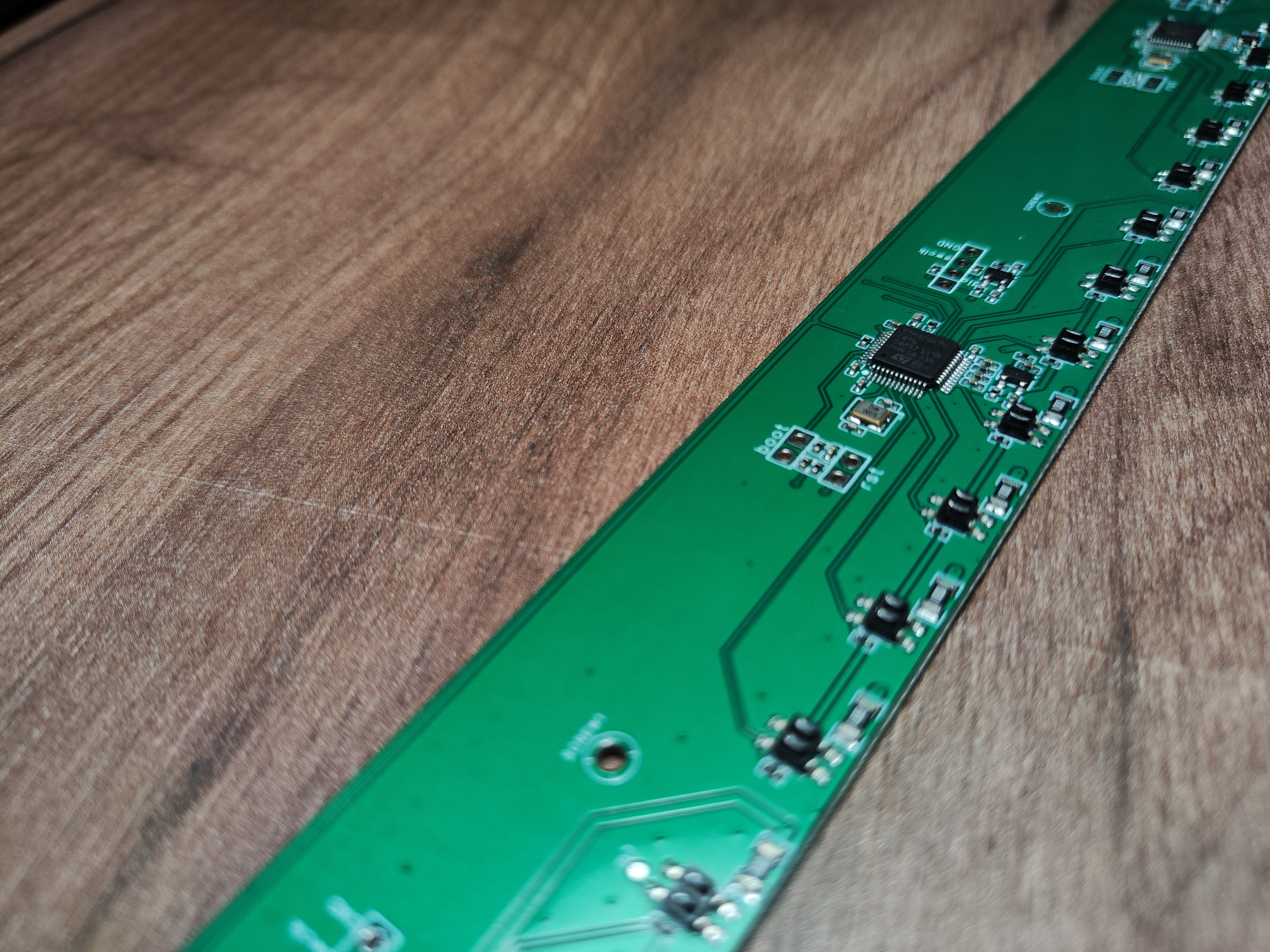
A bootloader has been added - the main controller can be flashed directly via USB, without a programmer. And all microcontrollers with sensors can be flashed from the main controller.

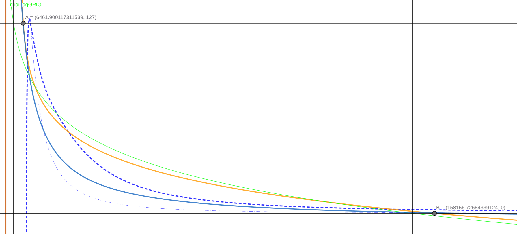
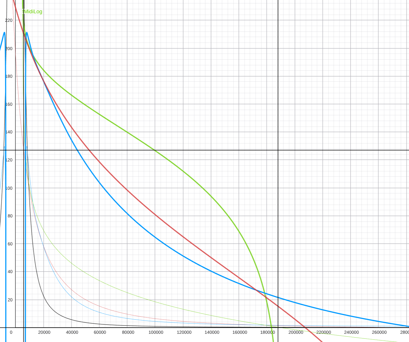
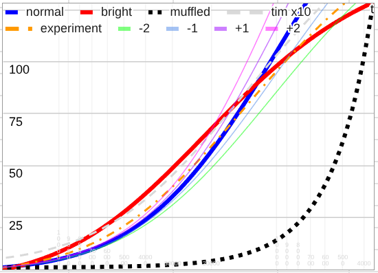
I played around with the velocity curves - in the end, I liked the option of calculating the hammer energy based on its mass the most. It seemed more plausible.


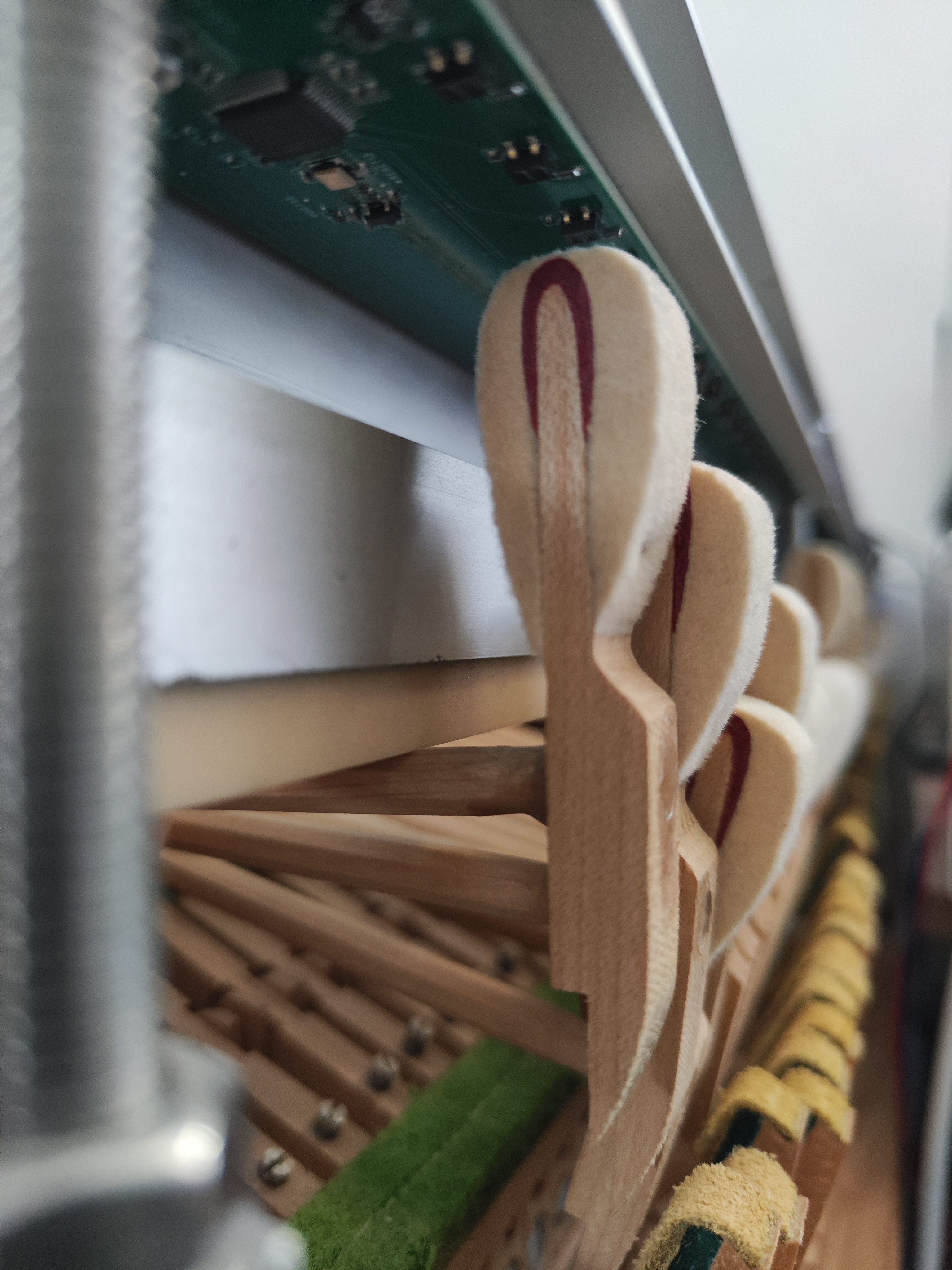
The keyboard response latency is still low - 30-50 microseconds. Hi-Res MIDI support - I estimate there are around 6000 velocity levels, maybe more. Currently, my sensors are mounted above the hammer felt. And I'm getting some minor crosstalk. They work in such a way that if two adjacent hammers move in the same direction, their velocity can increase slightly. I'm thinking of either painting the sides of the hammers with non-reflective paint, leaving the "working" space under the sensors, or moving the sensors to a different location on the hammer. I don't know yet, we'll see.

I also made a wavelet analyzer. Just out of curiosity. It allows you to examine phases, something you usually don't see in spectrum analyzers.
https://github.com/ScherbakovAl/wavescope


scherbakov.​al

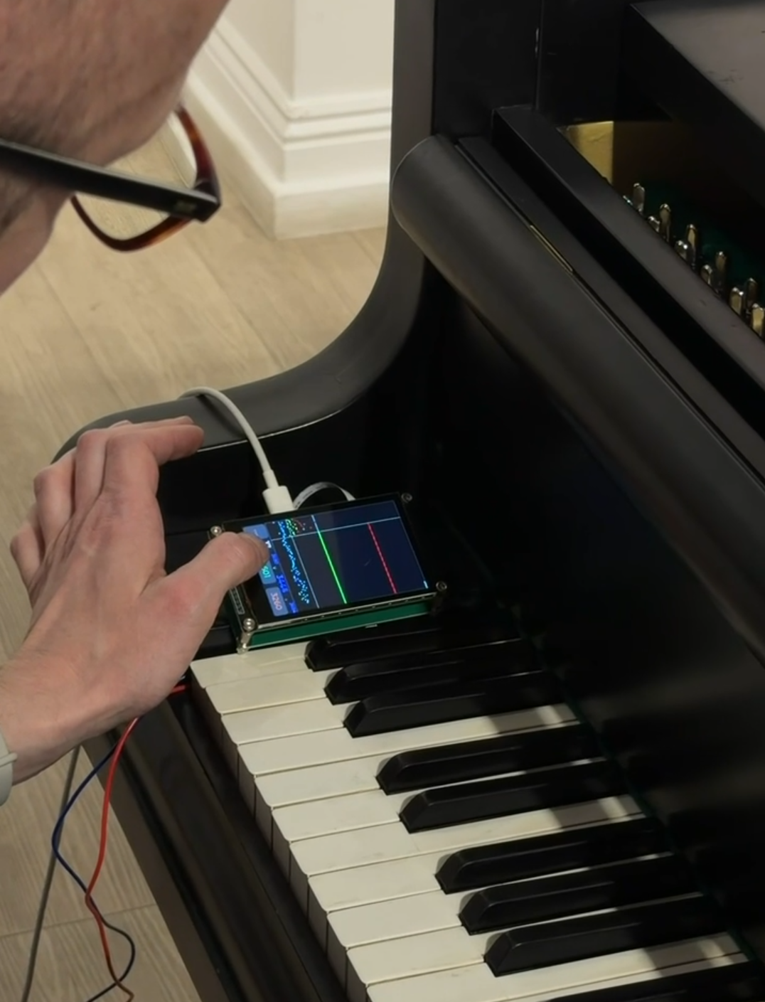
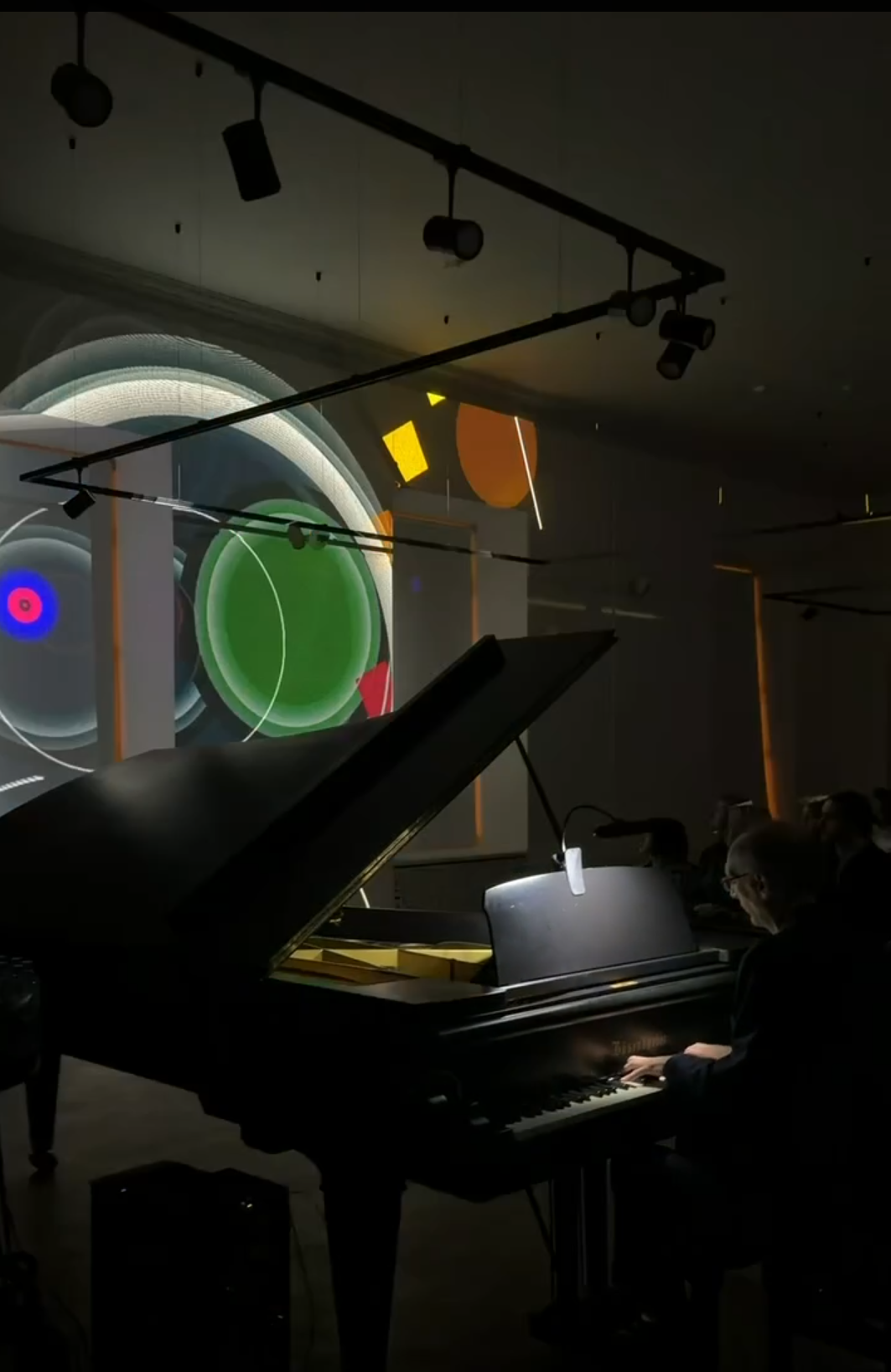
I was able to participate in an interesting event with this keyboard project. I modified my controller to fit under the keys of a Bösendorfer grand piano.

The piano was played by a pianist—the grandson of the artist Kandinsky. At the same time, a video sequence based on Kandinsky's ideas about the connection between form, color, and sound was generated by the computer from the piano keys. It was a pleasant event and a great learning experience for me.


PASHKULI

scherbakov.​al

Modified, as not at the hammers, rather under the keys (levers). What is the difference? Any videos?
Are those sensor just to detect velocity? 30 to 50 μs is good latency. 6000 velocity levels is over the top enough.
Proximity sensors? How the keys now (not hammers) hit the sensors? In a video above you show a hammer (held by your hand) hitting the sensors. How is it modified now (with proximity)?


scherbakov.​al

PASHKULI Modified, as not at the hammers, rather under the keys (levers). What is the difference? Any videos?
Under the keys—that's enough for visualization control. And sensors above the hammers are redundant in this case. Having sensors above the hammers is important for the pianist—to achieve good control and feedback from the action. Which was not required in that case. I can't post a video.

PASHKULI 6000 velocity
this is the base!

PASHKULI How the keys now (not hammers) hit the sensors?
The hammers barely reach the sensors - they are stopped by the stop bar

It is assumed that for playing, the sensors are above the hammers (above and below, as you wish) - to read the impact, and above/below the keys - to work with the dampers. The damper's "fall" speed is also present.

Incidentally, the problem is that if you make sensors for the keys, they'll fit the vast majority of vertical and horizontal keys—the key width is more or less standard. However, to position the sensors near the hammers, you'll likely need to custom-make them for each instrument model. The internal layout of instruments can be quite flexible.

For example, for a home instrument, boards were made with the distance between the pickups for the bass hammers being 13.55 mm, the left midrange being 13.37 mm, the right being 13.2 mm, and the treble being 13 mm. Otherwise, everything would have drifted apart. The number of hammers per section also varies greatly among different instruments.


PASHKULI

I see. So, it seems those are proximity sensors. But how would they detect the felt of the hammer if not touched\hit by it? Do you attach anything on top of the felt of the hammer? The hammer has a velocity at a given point. Does it mean that the sensor needs a minimum velocity (therefore proximity to it) by the hammer in order to set a minimum ppp (pianississimo) for example? Because fff (fortessissimo) is the closest\fastest maybe? So how the 6000 levels come to fit such setup?


« Previous Page Next Page »