DavisB
That's very nice!
Would you mind explaining how does it work?
Why does it have LM393 voltage comparator (another elements) per key/optical sensor, etc?

That's very nice!
Would you mind explaining how does it work?
Why does it have LM393 voltage comparator (another elements) per key/optical sensor, etc?
scherbakov.al congrats, that’s a great result already! How does it work, have you used an existing design or it’s your own design?
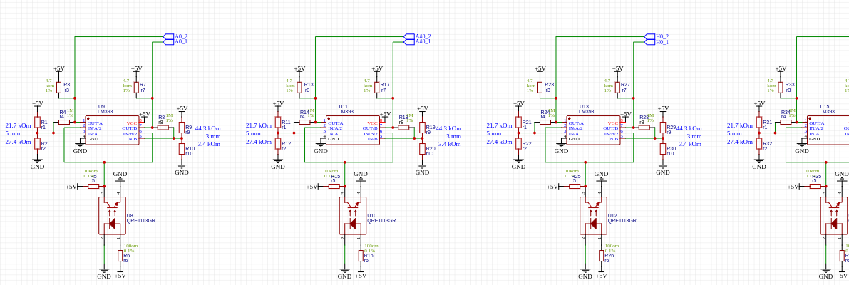
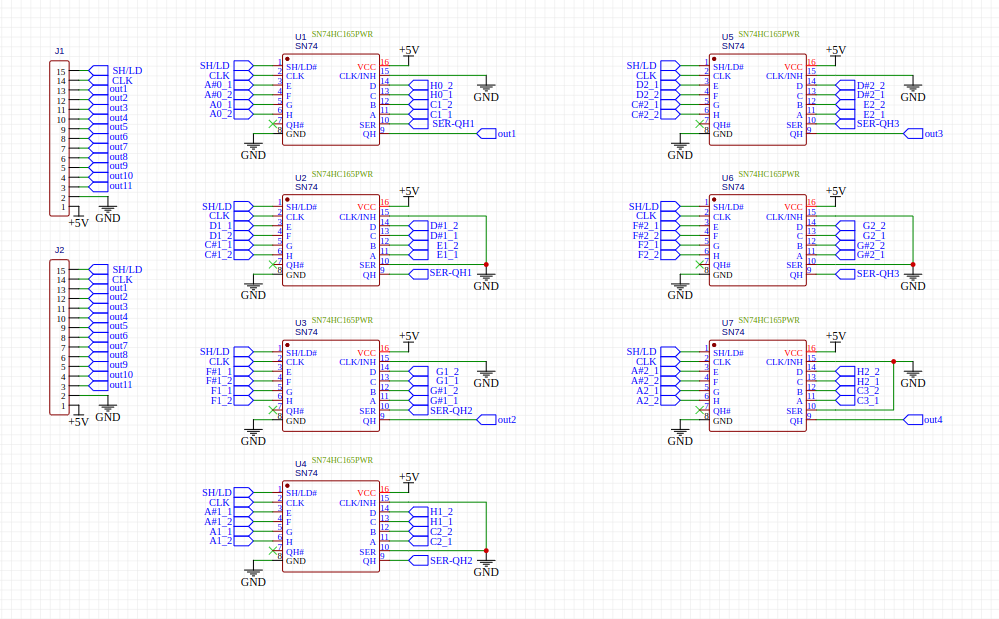
The optical sensor responds by changing the voltage to the distance to the hammer. This voltage is compared using a comparator. Data from the comparator goes into a shift register, which collects data from many sensors and transmits it sequentially to the microcontroller pin. In the microcontroller, if a signal is present, an interrupt is triggered in which data associated with the timer value and a specific sensor is processed. Next, a midi message is generated and sent to the computer.
CyberGene I would like to express my gratitude for the inspiration your project provided! A few years ago, digital pianos with real mechanics came out that I was drooling over, but the prices were completely unaffordable for me. And then you go and do something similar to Yamaha or Kawaii! And I thought, why not? And the Cybrid project showed that anything is possible!
Perhaps the circuit with comparators and optical sensors was borrowed. It is also quite common on the Internet (sites about Arduino are full of something similar). Next.. - shift registers and what follows them along the signal path had to be invented by myself. Some logic chips had to be added between the shift registers and the microcontroller to “cut” the signals. I also came up with the processing code myself. Cool C++ language. I like!
scherbakov.al I would like to express my gratitude for the inspiration your project provided!
Thank you 🙂
scherbakov.al shift registers and what follows them along the signal path had to be invented by myself.
That’s quite interesting although I’m not sure I understand it but I had to just read what shift register is, so maybe I need more time to think of it.
Do you use trimpots to set the comparator voltages?
Again, great job! And excellent playing 👏🏻
CyberGene
I suspect it's a parallel in, serial out shift register which captures results from multiple comparators and then shifts them out one by one using a clock signal. (it's another way to do multiplexing to save pins)
The main question I had is where does the two reference voltages come from? Are they fixed voltages same for all sensors (coming from resistors/voltage dividers?), are there trimpots (or digital trimpots), or something else entirely?
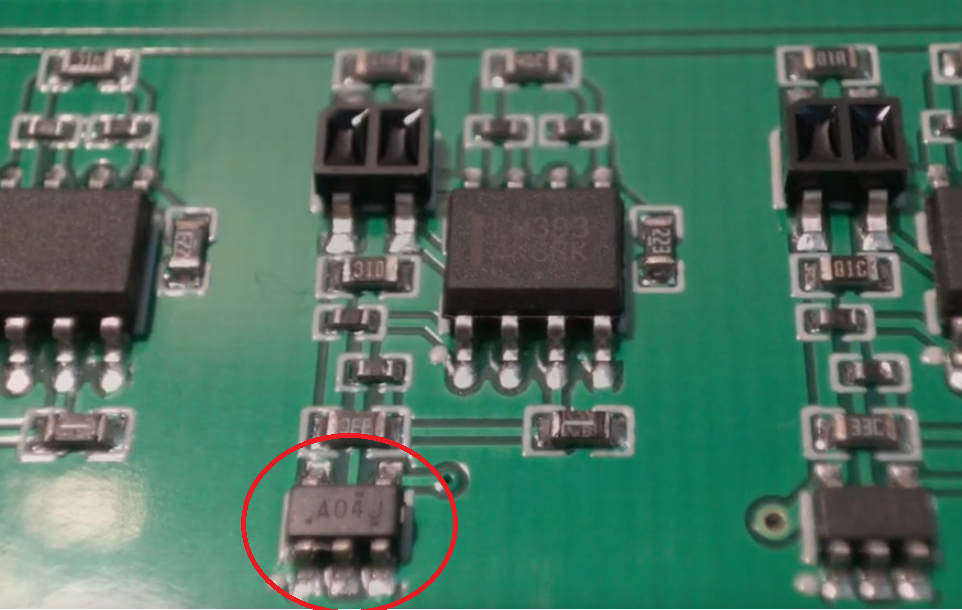
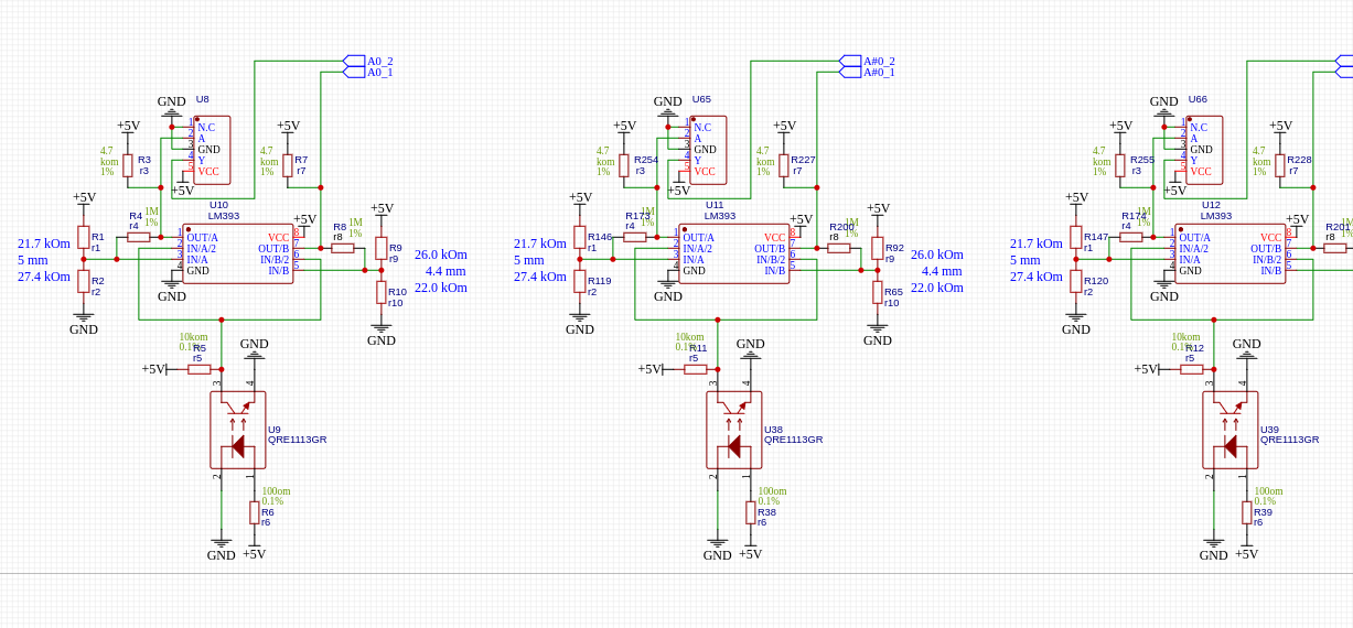
What's the element with five feet in the schematic?
I like this design (if I understand it correctly), as it's a simple design that can be done fairly cost effectively on a SMT line.
QRE1113 functionally equivalent sensors can be had in bulk (200+) for 6-7 cents a piece and LM393 3 cents a piece (or quad LM339 versions for slightly more)
The instrument works very well, very beautiful playing too. Great job!
DavisB The main question I had is where does the two reference voltages come from? Are they fixed voltages same for all sensors (coming from resistors/voltage dividers?), are there trimpots (or digital trimpots), or something else entirely?
That's a good question, as an object hypothethically at the same physical distance from two different sensors of the same type/model/fabrication process etc might not output (from the sensors) the same ballpark voltage. But this is where everybody already put in the hard yards in thinking and strategy. That's where the fun and challenges come in, which makes projects like this fun to get into.
Keeping track of the states, and keeping all possible conditions covered is certainly important. Otherwise end up with what happened with the NU1X. Niggling issues due to not having a system that covers all bases properly.
CyberGene That’s quite interesting although I’m not sure I understand it but I had to just read what shift register is, so maybe I need more time to think of it.
yes, DavisB discloses information.
CyberGene Do you use trimpots to set the comparator voltages?
I used trimming resistors to find out the required resistance value to switch the comparator at a given distance from the qre1113 sensor. This way I found out the required resistance values and subsequently used them on the boards.
DavisB The main question I had is where does the two reference voltages come from? Are they fixed voltages same for all sensors (coming from resistors/voltage dividers?), are there trimpots (or digital trimpots), or something else entirely?
Voltages are generated by resistors with predefined values. But the question is, are the voltages the same? Ha! now I don’t know) .. this needs to be checked. I didn't think about it and didn't know. Thank you. Need to check.
DavisB What's the element with five feet in the schematic?
"five feet" I don't understand because of the translation. Please clarify.
CyberGene Опять же, отличная работа! И отличная игра👏🏻
Heh.. the work is exciting, but the game.. something chattered from my student days.. I need to study more! Having practiced on this keyboard and learned pieces on it that we had to play at work, we, together with our oboist students, successfully performed at the competition. I am glad.
SouthPark That's a good question, as an object hypothethically at the same physical distance from two different sensors of the same type/model/fabrication process etc might not output the same ballpark voltage.
I have to check this out. Voltage is supplied in the middle. Maybe the tension gradually sags a little towards the edges. Perhaps because of this, the distances at which the comparators operate are shifted. This should be checked.
scherbakov.al Thanks for checking! For the photo-diodes and/or photo-transistors, if their performances etc are different in the different devices (of the same model and type etc), the output voltages could possibly be different, as in percentage differences could be significantly different. I got to order some of those devices to check out for myself later.
And in some other thread, I mentioned that I'm still on the long-haul wait (could be ages or forever) for absolute rotary optical encoders that a flat and compact enough - and haven't quite thought about physical coupling to key mechanisms yet hehe .... but the idea is to use absolute optical encoders for all or part of the tracking of key-mechanism position. Could possibly be used in conjunction with the optical velocity sensing device (based on that proximity sensing and timing measurement between two sensed pulses).
I have not yet measured the power supply on the comparators, but I remember that there is definitely some voltage drop on the LEDs. And on the other edge of the board from the voltage input there is some voltage drop. If you look at the LEDs through a camera (to see this radiation inaccessible to the eye), it seems like they all shine the same way. But I also looked at the boards with a thermal imager and yes, the sensors on the edges of the tool get a few degrees cooler than those closer to the power input. But when I installed the boards by adjusting the distance to the hammers, I did not visually detect any noticeable difference in the distance at which the sensors were triggered. Also, when playing, we have not yet discovered any differences in the operation of the central keys compared to the outer ones.
DavisB Функционально эквивалентные датчики QRE1113 можно приобрести оптом (200+) по цене 6-7 центов за штуку,
When I was selecting sensors, I found completely inexpensive Cny70 on aliexpress. I also had several original Cny70s. When testing “on the knees”, inexpensive sensors showed some noticeable scatter in their readings in contrast to the original ones. Also, by that time, I had found super cheap qre1113 on Ali and ordered them. A set of 300+ pieces cost about $40. But on the boards I decided to use the original qre1113, a set of which cost $200. And I even had to wait a couple of weeks until the next batch of sensors was manufactured.
The board diagrams look like this:
For the reference voltage for the comparators and power supply for the sensors, I used resistors with an accuracy of 0.1%
So far the current shortcomings:
The boards are heating up. Not much, but they become noticeably warm. If this is not particularly critical for the boards above the hammers, then it is not clear how the heat from the boards responsible for note-off and located between the keys and the mechanism will affect the mechanism. It takes time to test.
The stop rail for the hammers is made of an aluminum profile on which I cast polyurethane strips. And this rail turned out to be very loud when the hammers hit it. And I have already received dissatisfied feedback from my neighbors.
For now, the idea is to make the stop rail out of wood and perhaps choose another rubber-like material + body.
If the sensors above the hammers perform well and, in principle, their work suits me, then the sensors located above the keys (for note-off) require improvement. It is necessary to come up with some adjustment of the distances from the keys to the sensors. So far, the response points of the “dampers” are very uneven.
And while there is some bug, most likely in the code, sometimes the dampers do not work and some keys remain sounding (pressing it again clears this). Analysis required.
Thank you very much for taking the time to answer the questions regarding your design!
The five-feet, five-leg, five-pin element I was talking about was the red one. (hopefully the translation engine will pick up atleast one of the terms)
It's good to know in general that if you use tight-tolerance parts, that design with fixed resistor values can work quite well.
For the optical sensors --- if a particular diode shines a bit different to another one (from eg. neighbouring sensor device), and if the photo transistor of one device has different performance than another, then the voltages of the various different devices can/will be different. This probably where a testing jig or something might come in handy - with a computer controller striker that strikes at the same velocity, in order to tweak the second comparator reference voltage for purposes of getting roughly the same duration between the 'timing pulses'.
And the second comparator reference voltage for each sensor system would probably need to be recorded, in order to know the characteristics of each sensor device used. And then after that, the assumption would be that the characteristics for that particular device remain the same - which it might not remain the same - depending on age and/or other operating conditions.
DavisB The five-feet, five-leg, five-pin element
five-leg..yes) This is an inverter added to boards that monitor note-off events.
scherbakov.al This is an inverter added to boards that monitor note-off events.
That's clever, however this means that you basically have the equivalent of two-sensor action: you measure the velocity between the two points, and you generate a key-off event when the hammer is below the first point which means that you have to position that point to be halfway through the hammer travel, but then it won't allow for you to replay the keys without releasing beyond that point? A solution would be to set the first trigger point to be high enough (close to the second one) but then it will generate key-off on release way too easy?
Unfortunately, there is no measurement of the shutdown speed yet. Damn it! Now I think what prevented me from coming up with the idea of installing boards to turn off notes on the other side of the key lever and use the same circuit as when turning on notes? And without an inverter. And with speed scanning. I don't understand.
..I think I’m starting to guess why the dampers sometimes don’t work..