Skip to content

How to deal with hyperlocality in Savitzky–Golay filtering

JayKominek

CyberGene What are these middle peaks between the up-down movement?

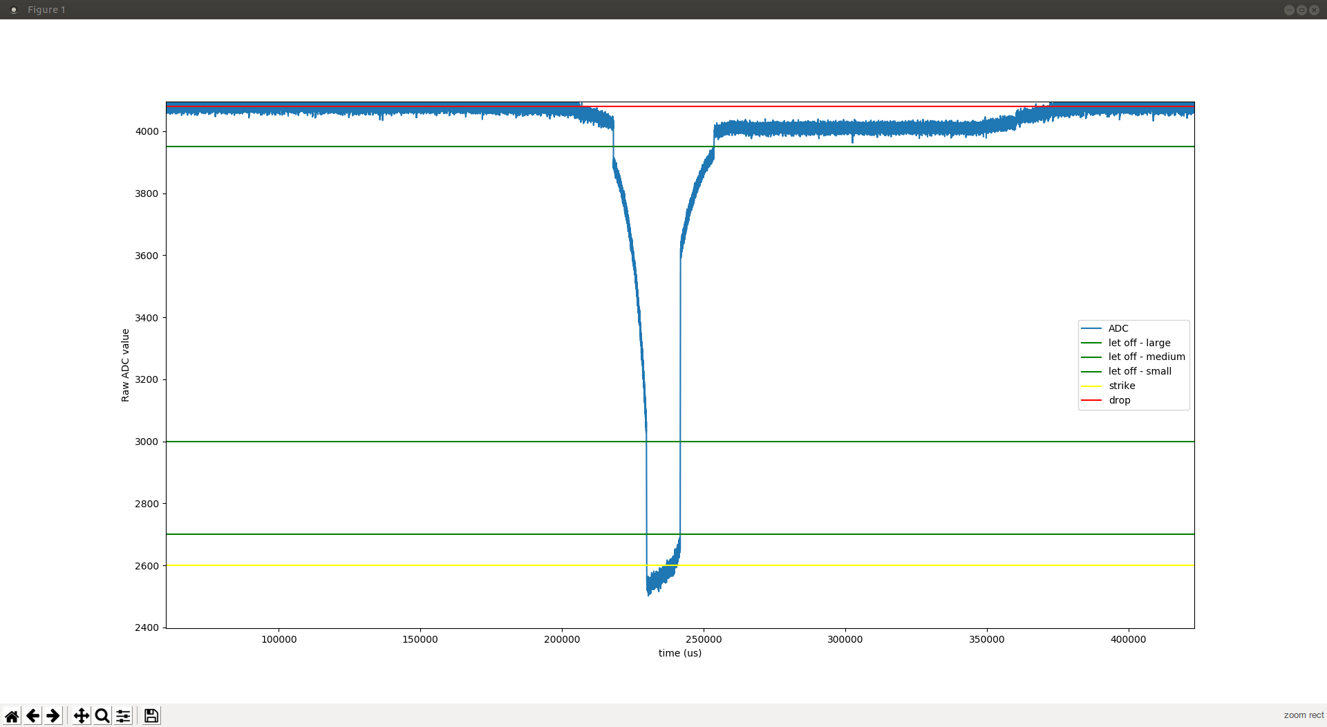
I would've guessed that whatever is being sensed is getting too close to the sensor. If you make it into physical contact with the surface of epoxy encapsulation, the signal will drop again, because no light can make it anywhere.

That aspect at least looks similar enough to what I saw with my sensors-on-hammers before I added some small additional spacing in front of the sensor.


RIP

JayKominek CyberGene What are these middle peaks between the up-down movement?

I would've guessed that whatever is being sensed is getting too close to the sensor. If you make it into physical contact with the surface of epoxy encapsulation, the signal will drop again, because no light can make it anywhere.

Yes, that is what I think it is.

CyberGene P.P.S. Ohh, you're measuring the shank which is why you get that strange oscillation then? Maybe if you measured the hammers instead, you would've taken a smoother curve. How about a low-pass filter to remove the oscillation?

I am indeed measuring the hammers, not the shank. And note that I consider a strike once I get "so close" to the sensor (yellow line) which is short of actually hitting it. So that "strange oscillation" is outside of the range I am considering for this experiment. Yet, there are other oscillations (noise), especially in the 12 bit data (the ADC has short of 9 ENOB, Effective Number Of Bits, so the lowest one are garbage). A similar problem occurs in the 8 bit data too (other file, or simply divide by 16 and take the integer part), so I thought to put the issue "out here" for other interested parties to mull about it.

To reiterate, my whole goal with the repository is to characterize the various sensors (for now only the 'RCA6, the others will come soon), and secondarily the Pico ADC. It might turn out to be a problem with either the sensor or the ADC, hence I asked Jay and STEM who are using different ones. Or it may be a problem with my data analysis, hence I asked the @luns and @xooorx who both seem to be very expert in that field.

Thanks everybody who took a look so far


xooorx

The problem is that your sample rate is too high for your Savitzky-Golay window length. The Savitzky-Golay is trying to fit a curve through whatever data fits in its window: That's all it can see at any moment.

With a faster sample rate, but the same kind of S-G length as was being discussed in the other thread, it is "zoomed in" on the noise instead of "zoomed out" on the desired signal.

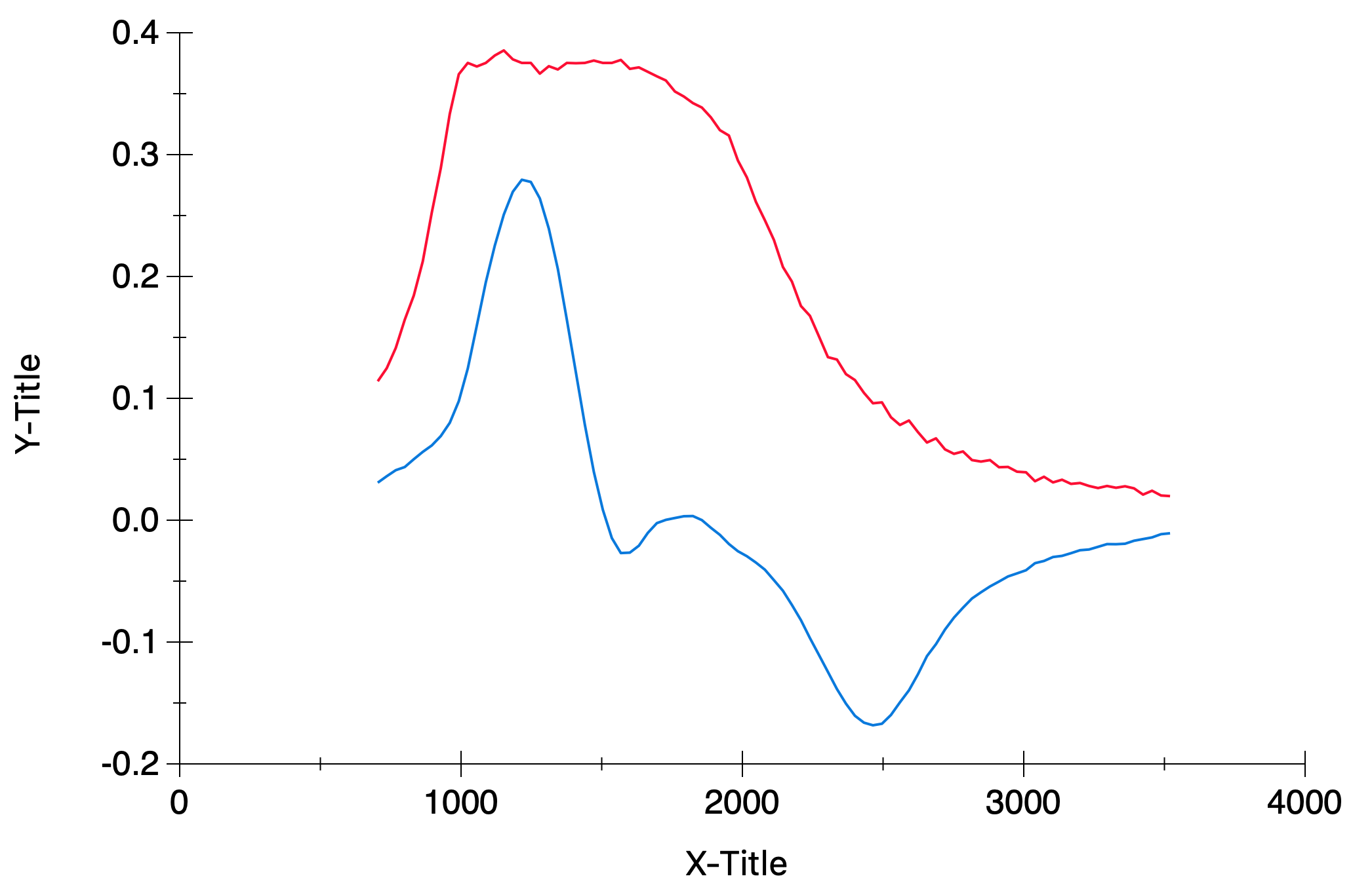
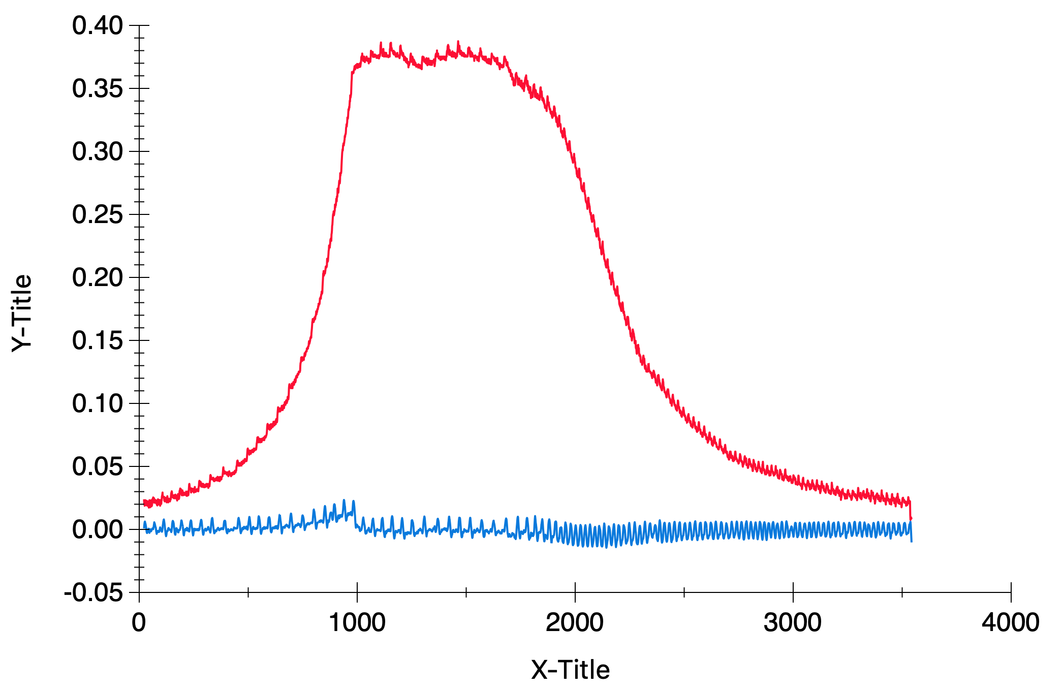
So here's some of your strike data (red) with a length 23 S-G (blue):

If we zoom in on this we can see that the Savitzky-Golay is doing a pretty good job... of differentiating the noise:

The solution is to increase the window length and/or decrease the sample rate so the S-G gets a better look at the signal. e.g. even just dividing the sample rate by 32 and keeping the S-G at 23 starts to look sensible:


RIP

xooorx The problem is that your sample rate is too high for your Savitzky-Golay window length.

Duh, that's obvious in hindsight, thanks for pointing it out to me so clearly.

xooorx The solution is to increase the window length and/or decrease the sample rate so the S-G gets a better look at the signal. e.g. even just dividing the sample rate by 32 and keeping the S-G at 23 starts to look sensible:

Part of the reasons of this exercise is checking if having such a fast sample rate is any useful, so I'll explore with longer window first -- and then compare the results with ones at (artificially) reduced sample rate. One important question to answer is the following. Can a S-G filter with a slower sample rate reproduce all the velocity MIDI values from 1 to 127 (and possibly even some of the higher resolution ones) or will there be gaps? The previous question should be interpreted "with natural key strikes", obviously if the key strikes are artificially slower, then we are just changing the time scale. We know that with the comparator approach, the answer to this question is "no", because there are gaps if the sample rate is too slow (*), since we need the sample rate to be able to reliably measure the small difference in flying time between (e.g.) MIDI velocities 126 and 127.

If with S-G we don't need such a fast sample rate that is great news, since only very few ADC converters support that, and even then with limitations. However I know how to make a back-of-the-envelope estimate of the needed minimum sample rate for the comparator approach (*) but I am not sure how to do that estimate with S-G. Do you?

Thanks again!

(*) here it is, for the ones who may have missed it in previous posts:

  • hammer speed at ff 5 m/s (may actually be even faster, probably up to 8 m/s) i.e. 5 mm/ms
  • let-off distance: 2 mm (may actually be even shorter, down to 1 mm)
  • time to flight: less than 400 us (potentially down to 100 us)
  • desired accuracy ~ 1% (to distinguish MIDI velocity 100 from MIDI velocity 101, more if one wants hi resolution velocities)
  • needed time resolution: less than 4 us (potentially down to 1 us)
  • sampling rate 0.25 MHz (potentially up to 1 MHz).

This sampling rate is ballpark of what I am using for this test, a factor of 10 faster than @JayKominek 's piano-conversion uses (which by the way is what I hope to eventually use).


JayKominek

I hadn't looked at your data zoomed in, previously. That's not nice gaussian noise you've got, there's some pretty awful structure. Something is wrong.

I believe the time values in your file are microseconds? You've got some roughly ~12.5kHz noise, and then some harmonics of it. You might be collecting 200kS/s, but the useful rate is well below that.


xooorx

JayKominek That's not nice gaussian noise you've got, there's some pretty awful structure. Something is wrong.

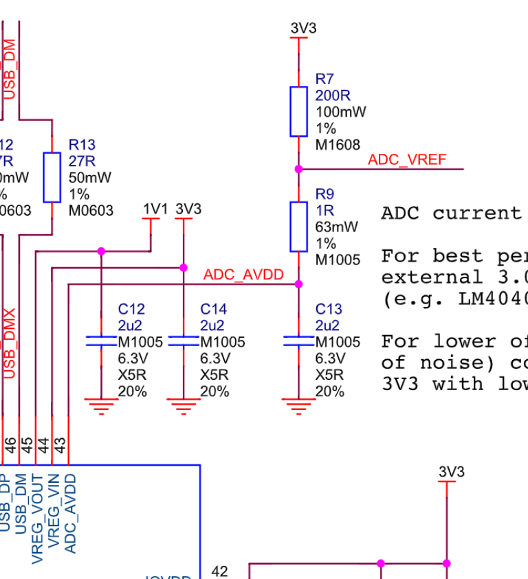
The ADC VREF on that board is just the switch mode power supply through an RC filter, which the datasheet admits is going to let through quite a lot of ripple/noise. It does also mention some things that can be done to reduce this.


RIP

Thanks to both of you!

JayKominek I believe the time values in your file are microseconds?

Yes they are (and the units should be specified).

JayKominek Something is wrong.

Ok, let's see what can I do to improve things.

xooorx JayKominek That's not nice gaussian noise you've got, there's some pretty awful structure. Something is wrong.

The ADC VREF on that board is just the switch mode power supply through an RC filter, which the datasheet admits is going to let through quite a lot of ripple/noise. It does also mention some things that can be done to reduce this.

The easiest thing would be to set the SMPS into PWM mode but that should have noticeable effect only at high load (and I don't think I am). However to do so I'd have to use GPIO23 which is not on a pin but on a test point on the back of the board and the datasheet mentions

TP4 GPIO23/SMPS PS pin (do not use)

without further elaborating why the "do not use" parenthetical. Alternatively, I had thought of powering it via batteries, but I believe the SMPS would kick in regardless to regulate the voltage to the desired level, so that sounded like a moot point (happy to be proved wrong about it). Using an external, high precision power supply was (probably still is) beyond my stamina level for this project, since I have none available and I'd have to find one, learn how to operate it, etc etc.

Moreover, while the noise is definitely there, it's mostly evident in the 12 bit sampling. Given this ADC ENOB is (slightly less than) 9, my eyes "automatically" deleted that information when reading the plots 🤣 -- probably too aggressively, since I now noticed that I did not pay much attention also to the about 2 bits of noise from the 8 bit sampling. Perhaps for the purpose of these tests I could just further reduce bit resolution and see what happens…. I'll think about it in the coming weekends.

Meanwhile, if @xooorx and @luns could chime in about the following (even with a "you can't say") that would made this part of my experimentation more clear

RIP If with S-G we don't need such a fast sample rate that is great news, since only very few ADC converters support that, and even then with limitations. However I know how to make a back-of-the-envelope estimate of the needed minimum sample rate for the comparator approach (*) but I am not sure how to do that estimate with S-G. Do you?

Thanks again everybody!


xooorx

RIP The easiest thing would be to set the SMPS into PWM mode but that should have noticeable effect only at high load (and I don't think I am). However to do so I'd have to use GPIO23 which is not on a pin but on a test point on the back of the board and the datasheet mentions

TP4 GPIO23/SMPS PS pin (do not use)

without further elaborating why the "do not use" parenthetical.

They're not saying to pull it high externally, they're saying to drive it high i.e. set it as an output and set it high from software. The "do not use" just means do not use TP4 as an external test point (it says so a bit further down).

Driving GPIO23 high forces the supply into PWM mode. It's at high load where this won't have any effect, since the supply will be in PWM mode anyway. At light load it should "greatly reduce the inherent ripple of the SMPS" at the cost of the board being a bit less power efficient.


RIP

xooorx Driving GPIO23 high forces the supply into PWM mode.

Ok thanks. Given the difficulty of doing that (I'd need to surface solder something on the back of the board and bring that something in front to make it accessible to drive it high when needed), I was wondering if instead powering the LEDs, phototransistors and ADC reference voltage off batteries would be better. It's certainly much easier to do with just existing leads and regular jumpers, and it is potentially a more stable source (since these are short-lived tests, I don't need to worry about the voltage of the battery dropping with time). Thoughts?


xooorx

RIP I'd need to surface solder something on the back of the board and bring that something in front to make it accessible to drive it high when needed

No... you just need to type some C code! The GPIO23 pin is connected to the PS mode pin of the regulator component. If your software makes GPIO23 an output and sets it to 1 then the regulator goes into PWM mode.

(Edit: That TP4 pad on the bottom of the board is also connected to GPIO23, which I think is what's distracting you here, but the "actual" GPIO23 is a pin on the processor not a pad on the board, and you can "drive" it from software).


JayKominek

Taking a look at https://pico-adc.markomo.me/ I'm not sure if switching the power supply mode will have any benefit. I'm also not convinced that is (only) SMPS noise on the signal.

It looks like AVDD could be disconnected from 3V3 and a linear regulator put in place. If I've got any appropriate parts I might give that a go in the next few days. Mostly for the lulz.

As it stands, I don't see any value in the RP2040's increased sample rate; if you need to downsample the 200kS/s signal by a factor of 16-32 in order to get rid of that weird noise, there isn't actually any benefit over collecting clean samples 16-32 times slower.


RIP

JayKominek I'm also not convinced that is (only) SMPS noise on the signal.

Would testing with batteries as I described above answer this question? I (or you) could do this pretty quickly. If you think it's useful, I can prioritize this test, sacrifice a CR2032 (=solder jumpers on it, since at the moment I don't have any suitable battery holder) and do the test in less than 1h late tonight or early tomorrow. You'll have the results tomorrow morning.

JayKominek if you need to downsample the 200kS/s signal by a factor of 16-32 in order to get rid of that weird noise, there isn't actually any benefit over collecting clean samples 16-32 times slower.

Of course. If anything, reducing the number of bits (while keeping the high frequency) might have some value, but the number requested to not "see" the noise might be too low to be useful anyway.

JayKominek As it stands, I don't see any value in the RP2040's increased sample rate;

Sure, if the system has these problems, its use for our purpose is a moot point, and we either need to find root cause and address the problem, or use a different ADC.

But the main question at this point still remain: can we generate all the needed MIDI velocities, without gaps, with a lower sample rate ADC, if we utilize S-G filtering? If so, great! If not, we need higher sample rate, or we'd be designing a subpar system.

xooorx That TP4 pad on the bottom of the board is also connected to GPIO23, which I think is what's distracting you here

You are correct.

xooorx If your software makes GPIO23 an output and sets it to 1 then the regulator goes into PWM mode.

I see, thanks. Then I could run this test easily. I will do it next time I power on the system, perhaps tonight, and report back.


JayKominek

RIP Would testing with batteries as I described above answer this question?

Disconnected from USB, if you connect a battery to the 3V3 net, I think that would work. Without power on Vsys, the switcher's EN pin won't go high, and it won't have any power to work with anyways.

I doubt you ever need to solder to the battery. Just get a decent length of wire exposed and tape the ends to each side of the battery, or compress it a bit.

RIP can we generate all the needed MIDI velocities, without gaps

I've not paid this any attention for a few weeks, because I'm not convinced this is necessary or sufficient for a quality device suitable of expressive performance.

A random number generate can spit out all the MIDI velocities; and a lot of well intentioned signal processing code can end up being fancy random number generators.

The goal probably looks more like "we need to measure pseudovelocities(*) with a dynamic range of 35:1, with about 10 bits of resolution across that range, so that we can maintain at least 7 bits of resolution after going through the velocity-to-MIDI mapping function specified in $paper and rounding to the nearest natural number".

(*): something with a ~linear relationship to real impact velocity.

As your goal stands, I don't know what satisfactory data would even look like.


RIP

JayKominek Disconnected from USB, if you connect a battery to the 3V3 net, I think that would work. Without power on Vsys, the switcher's EN pin won't go high, and it won't have any power to work with anyways.

Mmm, it's not clear to me what you are suggesting. If I power the pico via the battery, the SMPS is engaged anyway. So I was planning to power it via USB normally.

Assuming that the noise is in the analog part of the circuitry (including the ADC), my plan was to power the LEDs and phototransistors via the battery (rather than from the Pico as I am doing now). And use the same voltage for VREF_ADC. This way:

  • the LED illumination should be more constant (even though I doubt they can "flicker" at that frequency)
  • there should not be variation in the phototransistor signal other than what the sensor is doing on its own
  • the ADC should use this more constant reference voltage to compare and to power itself
  • and none of these will have any relationship with the SMPS

JayKominek As your goal stands, I don't know what satisfactory data would even look like.

Lack of that oscillations would be already an improvement, at least on the 8 bit measurements.

JayKominek Del Vento can we generate all the needed MIDI velocities, without gaps

I've not paid this any attention for a few weeks, because I'm not convinced this is necessary or sufficient for a quality device suitable of expressive performance.

It's definitely not sufficient. It might not even be necessary, but still worth investigating no?

JayKominek The goal probably looks more like "we need to measure pseudovelocities(*) with a dynamic range of 35:1, with about 10 bits of resolution across that range, so that we can maintain at least 7 bits of resolution after going through the velocity-to-MIDI mapping function specified in $paper and rounding to the nearest natural number".

Exactly! State as a question with different words (namely "is that possible with sampling frequency nnn kHz?") is what I am asking. And my back of the envelope math above answers half of that question with "no, that requires higher frequency sampling with the comparator approach". So I'm trying to find an answer to the other half, i.e. "what about the S-G approach?"


JayKominek

RIP Mmm, it's not clear to me what you are suggesting. If I power the pico via the battery, the SMPS is engaged anyway. So I was planning to power it via USB normally.

All assuming your battery is a reasonable voltage to power the RP2040 directly:

If you apply power to 3V3 (pin 36 of the Pico), that will be injected after the switching supply. The USB +5V comes in on VBUS, passes through D1 into VSYS and then the regulator's input.

Voltage might flow backwards through the regulator. Not sure. If it does (check with a meter?), grounding out 3V3_EN should help ensure it doesn't turn on and start doing things. Doing that might let you run off a battery, and be connected to USB, now that I think about it.

RIP Assuming that the noise is in the analog part of the circuitry (including the ADC), my plan was to power the LEDs and phototransistors via the battery (rather than from the Pico as I am doing now)

Won't hurt.

RIP And use the same voltage for VREF_ADC.

VREF is separated from 3V3 by a 200 ohm resistor. I wouldn't expect the battery to prevent noise on VREF unless R7 was removed.

Has somebody tried this that you're aware of? It just doesn't seem productive. But a coin cell will be safe, at least.


RIP

Ok, sooooo…..

JayKominek All assuming your battery is a reasonable voltage to power the RP2040 directly:

I tried with a new CR2032 which was a 3.38V before the test. During the test its voltage dropped to 1.7V and the pico won't power up. After the test the battery raised back to around 2.9V. I guess the whole thing needs more ampere than the battery can supply (and that was before I attached the SD card, whose SPI must consume some more). I guess I should have done some math before, but I didn't 😅 -- I thought to try with two D-cells in series, but I did not have any around that had enough juice to reach more than 3V together. So I tried with (another) new CR2032 connected as I described earlier.

JayKominek VREF is separated from 3V3 by a 200 ohm resistor. I wouldn't expect the battery to prevent noise on VREF unless R7 was removed.

Makes sense. Perhaps it can mitigate such noise a bit, otherwise I am not sure what they mean in the datasheet about that then. In any case, I tried it that way, since that was the only thing I could do (when you only have a hammer…..) -- For the tests below when I say "battery" I mean putting the battery between ADC_VREF and ground, and using it to power LEDs and phototransistors. Everything else is always powered with USB.

JayKominek Has somebody tried this that you're aware of?

Not that I know of.

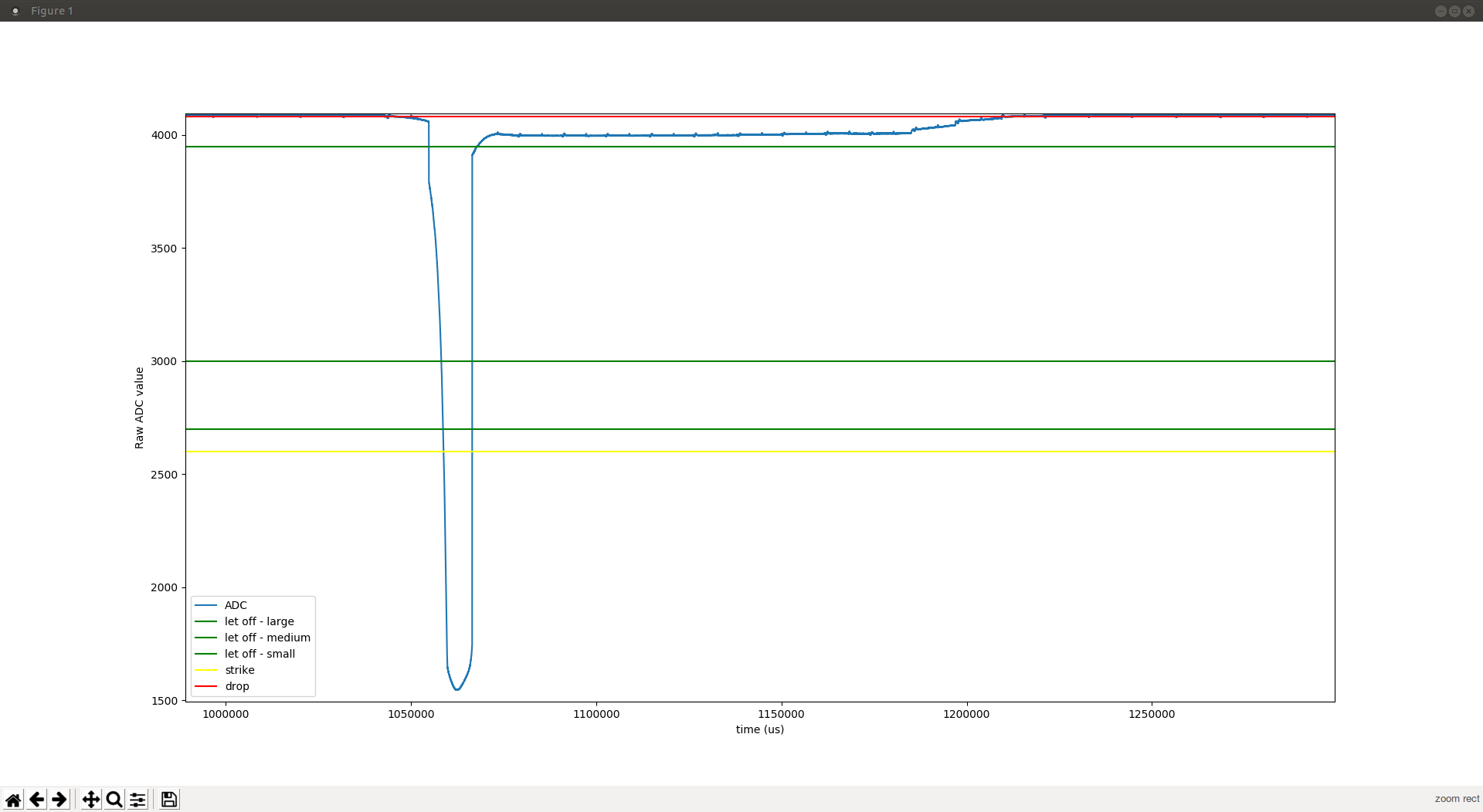
For reference, here is what a strike looks with USB power. You've seen this already:

And here is what a strike looks like with USB power and PWM forced on like @xooorx suggested (gpio_pull_up(23);)

And this is with battery (and still forced PWM):

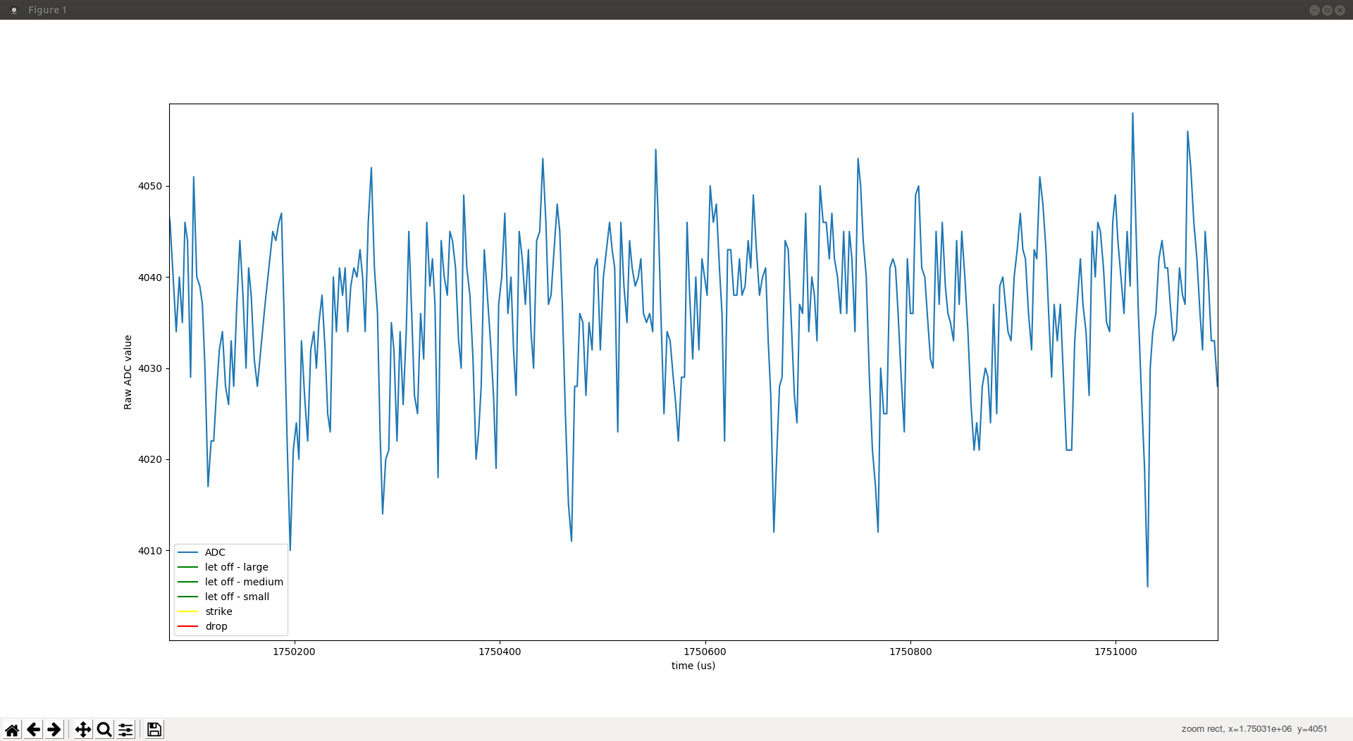
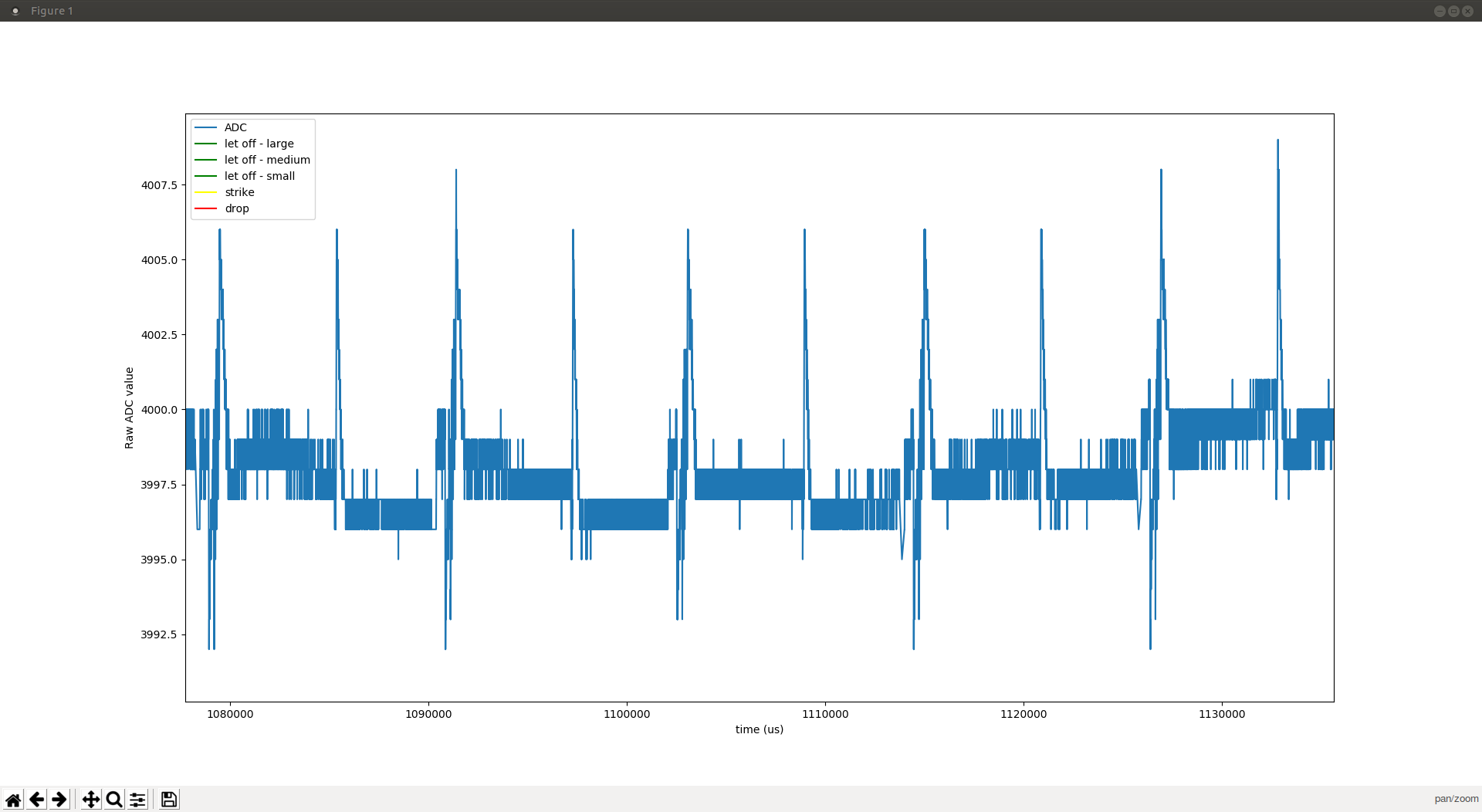
Now, you have certainly seen that the noise is shrinking. Here is a zoom in of the noise with the default USB power:

Pay attention to the vertical scale which is different among these plots. The horizontal scale is instead more or less the same. This is with PWM power -- marginally beter

And finally, here is a zoom for the battery.

Do notice that with the battery the noise is indeed much better, but not as good as it seems at first sight, since the whole signal is somewhat less (compare how the peak does not reach the yellow line in the strike plot), hence the S/N ratio needs to take the smaller signal into account. Yet, it's definitely better, since it's just about 10 ADC values of noise for about 4096-1800 = ~1300 ADC values of signal,

Whereas for the regular / PWM powered cases the signal signal is 4096 - 2400 = ~1600 ADC values and the noise between 30 and 40 ADC values: much more noise for only a bit more signal.

That D-cell tests seems appropriate…. It would be nice to have the code self-sufficient (rather than dependent on the computer issuing commands via minicom as it is now) so one does not need to attach the USB as it is now in my test setup: https://github.com/davidedelvento/no-OS-FatFS-SD-SPI-RPi-Pico

I don't think I'll have the time to do it this weekend.


RIP

RIP I don't think I'll have the time to do it this weekend.
If any of you does the test, please let me know (you'll need a suitable SD card and some way to attach it to the Pico, as described at https://github.com/davidedelvento/no-OS-FatFS-SD-SPI-RPi-Pico ).

If you only want to play with the data, you can download it here, it is 6MB, in the same format as described at https://github.com/davidedelvento/Mybrid/tree/main/data/RPiPico%2BEAITRCA6 (note that it is in binary, not MIDI, format, unlike I did earlier).


JayKominek

RIP Do notice that with the battery the noise is indeed much better, but not as good as it seems at first sight, since the whole signal is somewhat less

With the battery on there, probably acting as a large strange capacitor, the structure of the noise is greatly reduced. That starts looking like something you can apply filtering to usefully.

Probably the signal is smaller because your battery's voltage has been pulled down by… whatever weirdness is happening. So the LED is emitting less, and Vce on the phototransistor is lower, so Ice is reduced for a given amount of light hitting it. Vref dropping because it is also connected to the battery won't account for all of that.

I'd take it as a good sign.

RIP That D-cell tests seems appropriate….

Hmm, not sure if that will be better or worse. I thought they had quite high ESR, but when I went looking for information, (1) I couldn't find it and (2) what I did find suggested it was quite a bit lower than I thought. So I look forward to hearing what happens.


RIP

Wow! The battery did it.

As you anticipated the ESR was a bit of a problem (voltage dropped to 3.05V during the test) but I was able to complete the ADC capture without attaching a computer (and thus without knowing much if it was running correctly until after the fact). Yet, look how clean it is!!

Here is a detail:

Not sure about that residual 160Hz modulation, it might be the Pico itself or it may be some external signal. Possibly even light? The setup was a bit too precarious to perform in darkness, so I had the lights on (all LEDs, as matter of fact). Pointed as far away from the hammer area as I could, but still not in darkness.

I will post the data to https://github.com/davidedelvento/Mybrid/tree/main/data/RPiPico%2BEAITRCA6 in a few moments, but I had to let you know ASAP 😃


JayKominek

RIP Not sure about that residual 160Hz modulation, it might be the Pico itself or it may be some external signal. Possibly even light?

Yeah that's a pretty odd bit of noise. One would expect 30, 60, or 120Hz noise from lights or other AC sources in one's home.

Going wildly out on a limb, do you maybe write to the SD card at some multiple of 160Hz? Or maybe accumulate some power-of-two worth of writes to the card every 160Hz? I think most flash devices do weird buffering under the hood. 250kS/s, 1/160th of a second, 1562 samples. If you, hypothetically packed the two 12 bit samples into 3 bytes, that'd be 4686 bytes, a bit more than a 4k page.


Next Page »