Skip to content

A DIY hybrid piano without ADCs (purely digital sensors)

DavisB

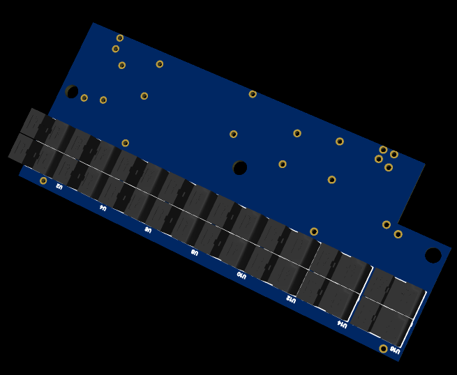
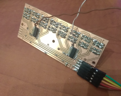
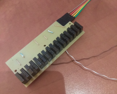
New experiment, with through-slot sensors this time:
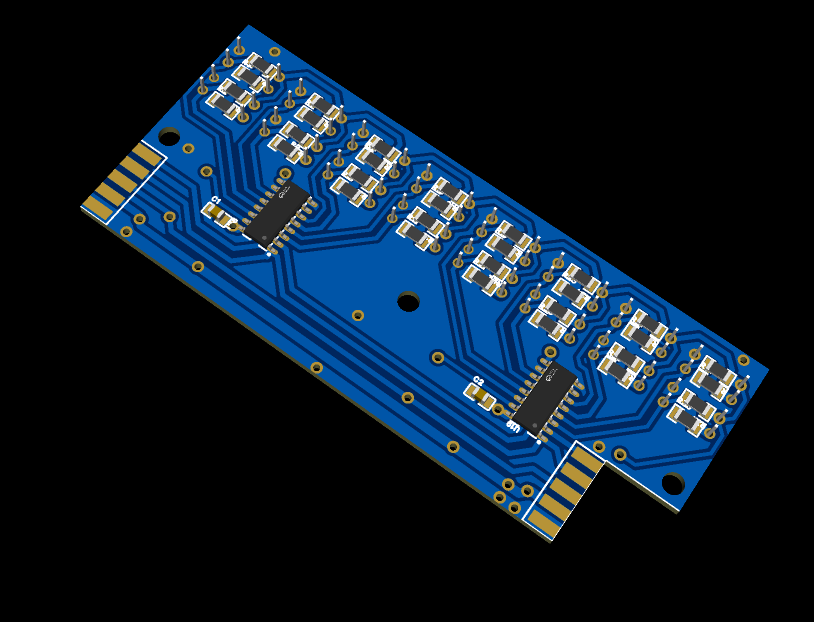

Design works, but have to integrate it with mechanics!

BOM:

  • 74HC165, parallel in shift registers 8cent x2 = 16cents
  • 1% 1206 resistors x32 = 8.62cents
  • iter8105 (Everlight Electronics), 11.5cents a piece x16 = 184cents (or alternative "noname" source in the exact same dimensions, 6.84cents x16 = 109.44cents)
  • 0805 MultiLayerCeramic capacitor, 2x100nf+10uf, 1.6cents
  • single sided copper FR4, for the area, roughly 40cents
  • pin header on both sides would be 2.5cent

Total cost for one board: 2.54eur (x11 = 27.8eur for whole piano) or 1.78eur (x11 = 19.60eur for whole piano) with 'noname' brand sensors (which i'm almost certain don't matter at all in this case)

There are extra cons as these are through hole components and they are quite big.
Smaller slot-through sensors are available in SMT packages, but those are significantly more expensive, and I suspect they might be harder to integrate with mechanics due to their size and small gap width and similar.

itr8307 SMT sensors are hard to beat price wise as those go down to 5-6cents a piece in relatively small volumes and one sensor is sufficient per key (which adds up to just 5.28eur in sensors for the whole piano)

This design would take up either 11pins or 22pins (depending if you chain up the two shift registers or not) + load pin + clock pin. I like this design the most frankly at the moment for it's utmost simplicity.

I'll probably be way less enthusiastic after trying to integrate them with the mechanics, but this is an approach i have to at least examine.
Paulo164

DavisB

In the installation manual of QRS PNOScan, they recommend to mark in black the sides of the keys with a black marker. I guess this is to minimize the crosstalk effect and maybe it could help also in your case.


vagfilm

DavisB

If I understand correctly, these new sensors act as simple switches (ie, transmit time not distance) but you need to have some fin/blade underneath the key that activates the sensor. You have two per key, and they are slanted (or if the fin is slanted) that gives two time readings, and therefore a velocity… If you add a third, you end up with something similar to the three sensor actions with rubber membranes. Am I following? Are you going to use the cybrid hardware for the digital readings?


DavisB

That is correct, a special element has to be moved through the slits/gaps of those sensors. I've yet to make those, so it's going to take some more experimentation!

Those elements can have special patterns carved out that enable multiple activations at multiple points in a key press... atleast in theory.

This board (times x11) has all the hardware necessary to get the digital signals out (via shift registers) with total 11 or 22 wires + clock/load wires (so roughly 14 or 25 i/o pins + some for pedals give or take) in total which go into right into teensy 4.1.

With 22wires, 2 output wires per board, clock signal would be 8 x sampling rate, say 8 x 30khz=240khz clock signal.
The number 8 is just the number of bits in each shift register chip (those can be chained together, to make a bigger 16bit shift register, but then it becomes a 16 x 30khz=480khz clock signal)

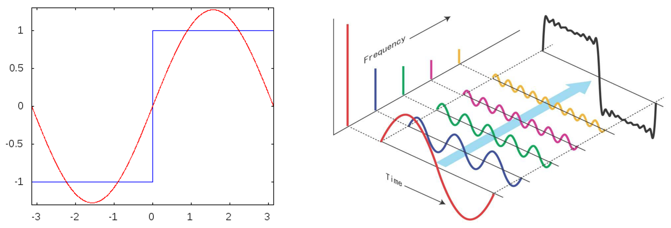
If the clock frequency becomes too high, noise might become a problem. With digital signals even fairly low frequency signals can be an issue if they have very sharp rise-fall times.

If a square wave is broken up into sine-waves you get loads of higher frequency content like this:

Or that's what I'm told!


candela

Thanks DavisB! This is very interesting, actually so interesting that I decided to create an account here to be able to reply. Your sensor board is very similar to the solution that's slowly been growing in my own mind for the past few months. The main difference in the electronics part is that I'm planning to use the Vishay TCUT1600x01 dual optocouplers instead of the pairs of ITER8105 components you're building your prototype from. Unfortunately, the TCUT1600x01 is only available as a surface mounted device which makes prototyping a bit more involved and I have not actually constructed any physical board as of yet. And I'm still mainly focused on designing the mechanical parts of the keys and action.

The reason for me to do this is to build a narrow keys midi controller and when I looked around I somehow didn't find any through-hole sensors narrow enough to fit without fanning out the keys in the back, which I very much would like to avoid. Thanks for pointing out these sensors! At 9.6 mm wide, they might actually work, at least for some kind of proof of concept, though they obviously move the pair of sensors much further apart from one another compared to the 0.8 mm distance on the TCUT1600x01.

One question that has been on my mind is whether Schmitt triggers ought to be used to clean up the signal from fluttering between on and off when going from one state to the other? This is also suggested in the data sheet for the TCUT. I see that you don't do that so I'm wondering how that is working and if Schmitt triggers would be unnecessary? (I'm in way deeper than my previous electronics knowledge here, so I really don't have much of an idea of what I'm doing.)

Would you mind sharing the circuit diagram, please? It's mostly clear from just watching the images, but still?


vagfilm

Thanks for the confirmation. Your project looks promising: no ADC, only timing signals, and without all the cabling of the original Cybrid. Shift registers are more than a bit (pun intended) above my paygrade, so I am rooting that you are able to pull this project through.


candela

Regarding the shift registers. I've been looking at the same component and you need to account not only for the time to do the serial out of 8 bits, but also the parallell in operation and the inhibit, which means it will take more than 8 clock pulses per cycle.


RIP

candela The reason for me to do this is to build a narrow keys midi controller and when I looked around I somehow didn't find any through-hole sensors narrow enough to fit without fanning out the keys in the back, which I very much would like to avoid.

If you are okay with the optical with ADC approach, the QRE1113 exists (with same size/footprint!!) in both through-hole and surface mount (SMT) variants! It's really tiny to definitely fit even with unreasonably small keys that you might want to build, but not so small to be unmanageable (especially the through-hole version). In fact that is why it's my favorite sensor. See https://github.com/stem-piano/sensor-systems/tree/main/qps (and links back to this forum) for details


candela

Thanks for the input, Del Vento! I did look into these approaches last year before starting my own project. My reasons for choosing a slit/fork type detector over a reflective one are mainly to avoid the ADC step and not having to recalibrate when IREDs go dimmer over time, reflective surfaces get dirty etc. Making the whole controller from scratch in contrast to transforming the action from an acoustic instrument also gives me the freedom to design the action parts myself to suit the sensor type and not the other way around. (I have access to a cnc mill, laser cutters, 3d printers, good wood and metal workshops etc through our local makerspace.) I did consider several options but settled on an all-digital signal chain with simple shift registers months ago and would need very good reasons to change that.


RIP

candela Thanks for the input, Del Vento!

You are most welcome!

candela y reasons for choosing a slit/fork type detector over a reflective one are mainly to avoid the ADC step and not having to recalibrate when IREDs go dimmer over time, reflective surfaces get dirty etc.

Got it. For the ADC, if you are designing it yourself, I understand. Digital is certainly easier and more stable (that's why our computers, music, video, etc are basically all digital, despite years of analog head-start and occasional claim of its comeback). In fact, the project too is mostly digital, besides the initial position sensing.

For the calibration.... One of the main goals of these projects is to make that calibration automatic at startup, because it's all (mostly) multiplicative (light at key-at-rest get dimmer -> it's equally dimmer also during play). In addition a simple "play-all-keys" additional calibration can add the "closest it can get" step, probably necessary every several years only.

candela the freedom to design the action parts myself to suit the sensor type

DavisB I like this design the most frankly at the moment for it's utmost simplicity.
I'll probably be way less enthusiastic after trying to integrate them with the mechanics, but this is an approach i have to at least examine.
That's very cool. Just make sure you don't underestimate the complexity of mechanical calibration and don't overestimate its stability -- but perhaps you @candela have already done that.

candela The reason for me to do this is to build a narrow keys midi controller

Since I'm also interested in exploring narrow-keys keyboards, I'm looking forward to see your progress. Once you start building things, please post pictures and design files somewhere (a new thread here, github, whatever you want) and ping us all or at least me 🙂


RIP

@DavisB @Paulo164 @vagfilm @candela I moved this discussion here since it's not relevant with the original Cybrid thread anymore. That had the side effect of unsubscribing you, so click on the "Following" button on the top-right if you wish to resubscribe


DavisB

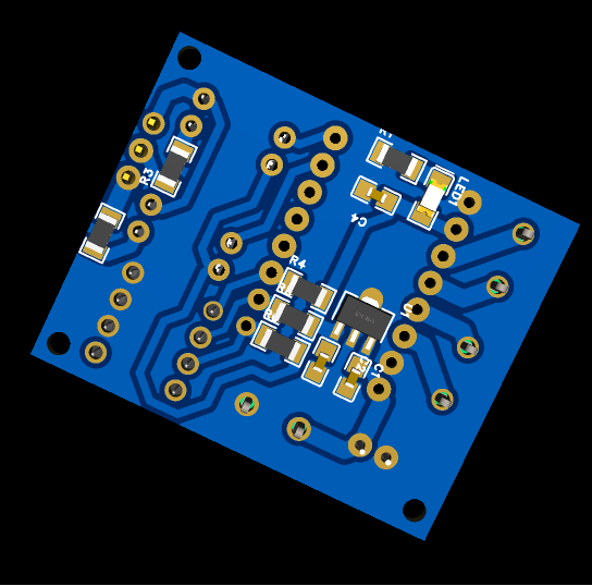
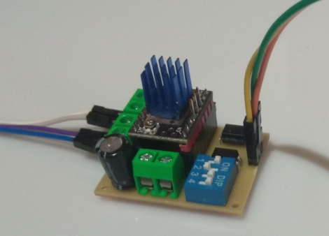
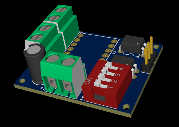
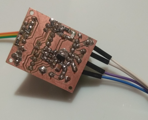
New experiment time - optically isolated stepper driver adapter for piano callibration!


Bom:

  • bigtreetech tmc2208 driver v3 = 2eur
  • Screw terminals, 2p 4 cents x3 = 12 cents
  • EL817 optocoupler, 3 cents x2 = 6 cents
  • 4position dip switch, = 16 cents
  • 78L05 linear voltage regulator = 2.5cents (used to convert 24v->5v, due to large difference it takes very little current to heat it up and smoke it)
  • 1206 red led status indicator = 1cent
  • 1206 resistors x8 = 2.2cent
  • 3x 0805/1206 decoupling caps = 2cent
  • 50v 100uF electrolytic cap, Rubycon = 53cent
  • fr4 one sided copper = 20 cents

The purpose of this adapter is to avoid using a breadboard and to hopefully avoid frying teensy by having a bit of isolation between it. Thus the stepper is wholly powered by independent 24v supply. Or that's the idea.

The idea is to use this to measure that all keys trigger optical switches at the same distance and that the distance between trigger1/trigger2 is the same, or atleast similar enough.
If not, perhaps use the information to account for that in software. Ie. have a measurement diagnostics tool that couples sensor reading values with distance of how deeply a key is pressed.

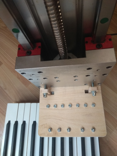
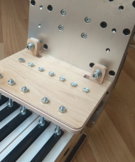
This is how it looks in practice. Ideally it would also have a second axis and it would automatically press all the keys - octave by octave or key by key and confirm that the instrument is up to spec.


DavisB

candela

The reason for me to do this is to build a narrow keys midi controller and when I looked around I somehow didn't find any through-hole sensors narrow enough to fit without fanning out the keys in the back, which I very much would like to avoid.

We are in the same boat then!

One question that has been on my mind is whether Schmitt triggers ought to be used to clean up the signal from fluttering between on and off when going from one state to the other? This is also suggested in the data sheet for the TCUT. I see that you don't do that so I'm wondering how that is working and if Schmitt triggers would be unnecessary?

AVR mcus, teensy 4.1 and others usually have schmitt triggers built in into GPIO inputs, or you can optionally enable them, as far as I know.

Perhaps you might want an external schmitt trigger if you want to have an explicit control of the analog threshold hi/lo values.


RIP

@candela The reason for me to do this is to build a narrow keys midi controller and when I looked around I somehow didn't find any through-hole sensors narrow enough to fit without fanning out the keys in the back, which I very much would like to avoid.

DavisB We are in the same boat then!

The QRE1113 is narrow enough and has a variant that is through hole (and another with the same footprint that is SMT, so it's an ideal part for experimenting easily at home and then get it assembled at scale professionally).

By the way, I'm now experimenting with WNG action parts (in my opinion much better than the Renner and Tokiwa one people are arguing/raving in the other threads). Possible to make 6" octaves, but really hard getting below that (and definitely impossible getting to 5.5" with "regular assembly") -- once I finish with the regularly sized project (hopefully just a weekend or two), I'll post some updates on this with some creative "non-regular" assembly I've been thinking of. Stay tuned!


DavisB

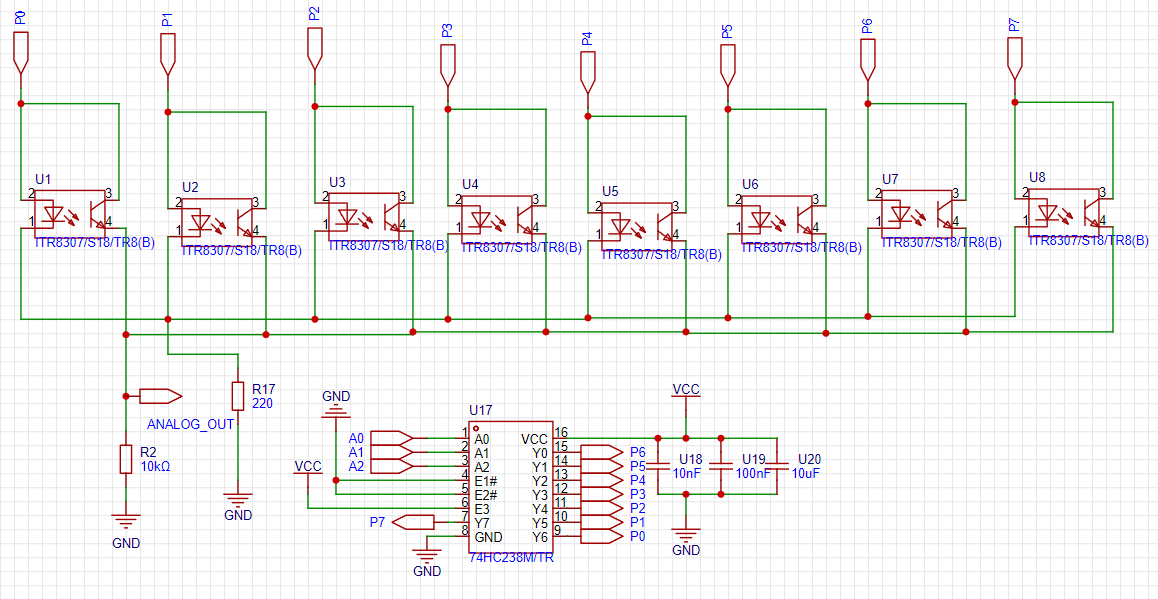
Is there something I'm overlooking, but why isn't 74hc238 isn't used for multiplexing (in analog sensor case)?

  1. Reduces power consumption to 1/8, because only every eigth LED is lit up.
  2. Need only 2 resistors for 8 sensors (one for led and one for photo transistor which are shared by all 8), and decoupling caps for the IC.
  3. Reduces light crosstalk (there's 7 unlit sensors on both sides)
  4. Can be chained together to create 1-to-16 or 1-to-32 mux.

Even in 1-to-8 case this leaves only 11 analog signals to be multiplexed or processed. (11 boards of 8 sensors)

74hc238 is bit more expensive (12cents) than the ubiquitous inverting 74hc138 (these go as low as 5cents a piece)


ambrozy

Because you need high time resolution for analog sensors? Something like at least 10khz on each key I think. It is certainly possible to do it like that but you are asking for a problems because it's getting into RF territory where one wrong decision in PCB design can make it not work at all, and also you would need some great ADCs and very fast sensors.


RIP

DavisB multiplexing

I actually have not given much consideration into that, and just accepted what others have done, so let me bring @gzpiano and @JayKominek into the conversation, but here are my speculations

DavisB Reduces power consumption to 1/8

This is a nice-to-have. For constant current driver (which IMHO is what should be used for this project) where there is no current-limiting resistor, the power consumption is not that much, so I'll take the saving, but not a big deal.

DavisB Need only 2 resistors for 8 sensors

Again, you are thinking of the 16 resistors needed for a circuit with individual current limiting resistors, which IMHO you should not. See my quick take on this if you don't know what I am talking about

DavisB Reduces light crosstalk (there's 7 unlit sensors on both sides)

I think that's a great advantage, and the reason why you grabbed my attention even if I came to the computer with the intention of shutting it off, rather than posting another message 😃

Possible problems I see from the LED driver point of view: I am not sure how a constant current setup would react to this kind of multiplexing. The LED themselves are able to switch on and off at that rate no problem. I don't think their lifetime would be affected by the number of on/off cycles, if they are not subjected to current spikes. In fact their lifetime could be extended by such a driving mode since it's typically rated in pure time spent in the on status. The question is if one can make the parasitic impedance of the rest of circuit small enough to not subject them to current spikes (I think that is feasible) and to have the current stabilize quickly enough for the readout, since you don't want to use the sensor until you know the lighting from LED is constant. I think the most important questions are how much current can the mux carry, what is its parasitic impedance and how that would affect the the speed of switching the LEDs on and off?

As "gut feeling" (my EE is just amateurishy) is that this can be done with some work. Simply there is not such a large advantage for people to have (so far) thought about it. I think reducing crosstalk is very valuable benefit and worth investigating this more, especially for small-size keyboards, where the sensors are closer to each other.

See video number 29 for a take from @gzpiano about crosstalk.

See also my comment and @gzpiano somewhat dismissive one (which would apply less on reduced-size-keyboards) at things to consider number 6

Since I'm at it, let me comment on

RIP By the way, I'm now experimenting with WNG action parts

RIP I'll post some updates on this with some creative "non-regular" assembly I've been thinking of.

to just say that I've done very little about it, and I've found it's difficult for reasons I'll explain later because

RIP once I finish with the regularly sized project (hopefully just a weekend or two)

this is taking longer than I hoped (but it's making progress, as I reported in the other thread)


RIP

ambrozy Something like at least 10khz on each key I think.

LEDs can easily switch in the MHz regime, and probably much higher. There are multiplexes on the sensor side anyway, because otherwise one would need too many ADCs and those are too expensive and complicated (and would in turn need too much MCU computing power to deal with them)….

ambrozy and also you would need some great ADCs and very fast sensors.

You need all of that anyway

ambrozy it's getting into RF territory where one wrong decision in PCB design can make it not work at all,

These numbers are considered VLF and have wavelengths in the tens of km (miles) which mean any mistake on the cm (inch) size of the PCB is going to be irrelevant. I mean, one still has to correctly design the PCB to avoid it working as an antenna for the plenty of signals that exist at the wavelengths of its size, but having it work in the tens or even hundreds of kHz (and perhaps even low MHz) range is not going to be a big deal


JayKominek

this depends heavily on the physical realization of the circuit.

if what is depicted is entirely on one PCB with a ground plane, then eh, it's probably okay. you've moved the mux that was designed by Very Smart People out of the ADC and onto your PCB, and made a lot of the signal loops larger, and given yourself synchronization problems to worry about. you can probably overcome all of that.

if the P0..7 nets are pieces of copper wire leaving the board, coming from some more central circuit board to sensors on each key (which seems necessary, because most actions don't have all 88 keys spaced exactly the same distance from each other, but maybe you're lucky?), then those loops are going to act as illegal radio transmitters.

it isn't the 10kHz sampling rate, or the 80kHz mux switching rate that will matter, it'll be the speed of the edge(s) generated by the 74HC238 as it switches the signals on and off that generate the noise. the '238 switches fast enough to be used in circuits of many, many MHz, for which your wires will be passable antennas.

RIP I am not sure how a constant current setup would react to this kind of multiplexing.

probably best to make the driver aware of the switching of the mux, so that it can turn off, allow the mux to switch, and then turn back on. and you're going to want a very well tuned control loop in your CC driver so that it can settle fast enough.

RIP I don't think their lifetime would be affected by the number of on/off cycles, if they are not subjected to current spikes. In fact their lifetime could be extended by such a driving mode since it's typically rated in pure time spent in the on status.

yes the LEDs would be happier and last longer.

and as you alude to, while the LED might be happy to switch extremely fast, it isn't necessarily being driven in a fashion which will allow it to do so.

the LEDs transmitting data at megahertz aren't doing it with a voltage source on one side, a resistor on the other, and a meter of copper wire inbetween.


scherbakov.​al

DavisB

That's interesting. I want to try to test a similar scheme. But I'm still forced to finish the renovation of the house. What if you use something like CD4022B instead of 74hc238?(maybe there are faster options..) Then you will need 1 channel instead of 3 channels to switch. I'll have to check it out..


Next Page »