AlexanderBunt
RIP Yeah doing that now. Trying and see what will happen. Thanks for the help.
Will keep you posted.

RIP Yeah doing that now. Trying and see what will happen. Thanks for the help.
Will keep you posted.
RIP And remember: premature optimization is the root of all evil, so just try it, see what happens
Wise words, as always...
If I want to use your sensor board, where do I have to place which resistor and how does the CNY70 sensor be placed on the board?
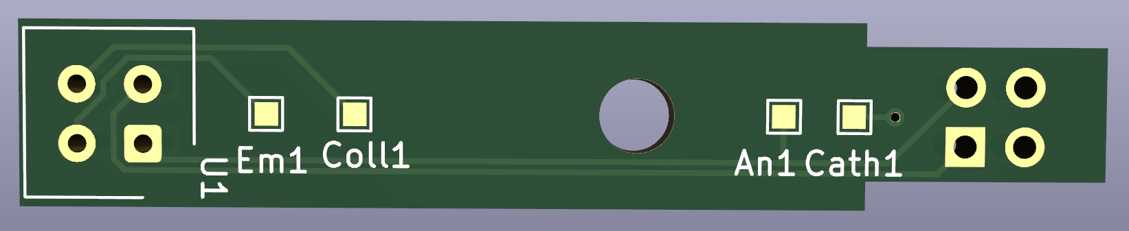
For example this board:
I think the led resistor should be on Em1 - Coll1, and the phototransistor on An1 - Cath1. But am I right?
AlexanderBunt If I want to use your sensor board,
Have you tried to use KiCad for the purpose? All the information you are asking should be there.
Start https://docs.kicad.org/5.1/en/getting_started_in_kicad/getting_started_in_kicad.html if you don't know what I'm talking about.
PS: sorry if I sound too blunt, I'm just trying to protect Jay from too many questions (including my own 🤣)
AlexanderBunt That appears to be my 2020-offset-1x board. It doesn't have any resistors on it. The labeled pads you're seeing are test points.
The LEDs in my design are driven by a constant current source, so there aren't any resistors used to control LED current. Similarly, the phototransistor collector is attached directly to +3.3V, and the emitter feeds into a transimpedance amplifier. So there's a gain resistor for that, but it is located adjacent to the relevant op amp.
The orientation of the sensor is easy enough, though. The markings on one side of the CNY70 should be facing left in that image, away from the U1 silkscreen.
My document here https://github.com/jkominek/piano-conversion/wiki/Analog-Stage-Theory-of-Operation explains how my system powers the CNY70 LEDs, and then gets/makes use of the signal from the phototransistor.
I am just 'finished' my first version of the Hybrid Carillon. I must say, apart from the power, which I don't know how to get right, it works very well… I used one Teensy 3.5, with 4 16x multiplexers. So I have 64 sensors put through just 4 analog inputs on the Teensy. I know, this seems to be far to slow, but its not. Or at least, not mentionable…
The only problem I am facing now, is the power. For now I use breadboards for the connections. This is of course a temporal solution and I want to change this to custom made PCB's. But for the power I use two 'breadboard 3.3v/5v' power supplies for 48 sensors. These offer 700Ma. And I know 1400Ma can not be enough for 48 sensors, because the sensors each need 50Ma for as far as I know…
But which solution should I use for this problem? Maybe you guys have a clue…? @JayKominek @RIP @CyberGene
Hi AlexanderBunt , great news, well done!
Perhaps look at something like this:
https://www.soundimports.eu/en/mean-well-rs-100-24.html
That'll supply plenty of nice and stable power, yet outputs 24V DC. So some conversion/regulation electronics are needed to give you the 5V and/or 3.3V, whichever one you need.
Maybe there are other power supplies that would give you the voltages right away, like a computer ATX power supply with modified cabling. I personally like beQuiet! computer power supplies because they're decent and… drumroll… quiet.
Cheers and happy building!
HZ
AlexanderBunt Congrats for not giving up, feel free to share your progress video 🙂
As to power, I use an iPad charger which is 2.1 A and is ripple free (well, almost but better than any other power I tried). Take in mind that changing the USB cable that you use for power may change the resistance and hence the voltage calibration of the CNY70 sensors 🙂 Ask me how I know 😀
AlexanderBunt The only problem I am facing now, is the power. For now I use breadboards for the connections. This is of course a temporal solution and I want to change this to custom made PCB's. But for the power I use two 'breadboard 3.3v/5v' power supplies for 48 sensors. These offer 700Ma. And I know 1400Ma can not be enough for 48 sensors, because the sensors each need 50Ma for as far as I know…
Are you using optical sensors, like the CNY70? Do you want reliable dynamic control? If so, stability of the power supply to the LED is essential. If the power fluctuates, the light output fluctuate, and so the apparent distance that the phototransistor "thinks" the hammer is at fluctuates, and so the actual dynamics (and perhaps even timing) fluctuates. The stability is essential. All commercially available power supplies that I know of are not stable enough if you want to be accurate, even though you might live with their limitations as @CyberGene has done.
See https://github.com/jkominek/piano-conversion/wiki/LED-Power-Board for a simple solution (which has also a PCB already designed at https://github.com/jkominek/piano-conversion/tree/master/hardware/led-power and you may be able to order it already assembled from a PCB company.
PS: I assume you mean 700mA and 1400mA etc. Case is very important: A=Amper=current. The lowercase a seems to imply acceleration. Lowercase m = 1/1000. Uppercase M=1000, so a million more than you (most likely) meant
AlexanderBunt because the sensors each need 50Ma for as far as I know…
I assume you stuck with the CNY70s.
Their IR LEDs do not consume 50mA. Rather, they're current devices. They consume approximately 1.25V. (That does not mean they should be attached to an ideal 1.25V source!) And the 50mA value comes from the "Absolute Maximum Ratings" section. You want to give them less than that. I settled on 20mA.
I believe you were using the design where you put a resistor in series with the LED to control the current. That value, along with the forward voltage of the LED, will determine how much power is consumed by each of the LEDs.
Mean Well is a perfectly good power supply manufacturer, but I'd buy supplies much closer to what you actually need, rather than fiddling with trying to drop down from +24VDC to something small. (Anything which can do that without burning up will introduce its own noise and problems.) They manufacture a number of supplies which directly output +5VDC. Maybe even +3.3VDC, though I haven't checked their catalog for that. I suggest fully enclosed supplies.
Ideally, you'd want to have designed it to use a constant current supply for the LEDs, and chained them together in groups of 24. Without knowing exactly how you've done the physical wiring, I can't say if it is possible to go back to that at this point.
CyberGene As to power, I use an iPad charger which is 2.1 A and is ripple free
🤣
RIP you may be able to order it already assembled from a PCB company.
It has a number of through-hole parts, I doubt any of the inexpensive places will assemble the whole thing.
I know why you gave it the LOL 😀
But let’s say this, among the power supplies one can usually find at home, the iPad one is probably the best. I even found some website that cracked it open and analyzed it against many similar chargers and praised it for being designed way better than the rest and having more advanced circuitry to provide less ripple. I need to find the link. Of course there are probably better power supplies out there 🙂
Yes, typically 5V on a series of one 220ohm resistor and a 1.25V led. There remains 5-1.25=3.75V… then the current is 3.75/220=0.017=17mA.
Okay wauw thanks for the many answers! I will make a photo of the wiring when I am at my brothers house (thats where it's standing…), probably tonight. Don't panic when you see the absurd amount of wires haha.
JayKominek Mean Well is a perfectly good power supply manufacturer
Probably this…?
CyberGene Yeah I will make a short video of what I have now. Would be nice to see I think.
CyberGene I need to find the link
Found it: https://www.righto.com/2012/10/a-dozen-usb-chargers-in-lab-apple-is.html
The iPad charger almost eliminates the ripple; only a small blip is visible in the orange spectrum on the right. The noise level is low, although appreciably worse than the iPhone.