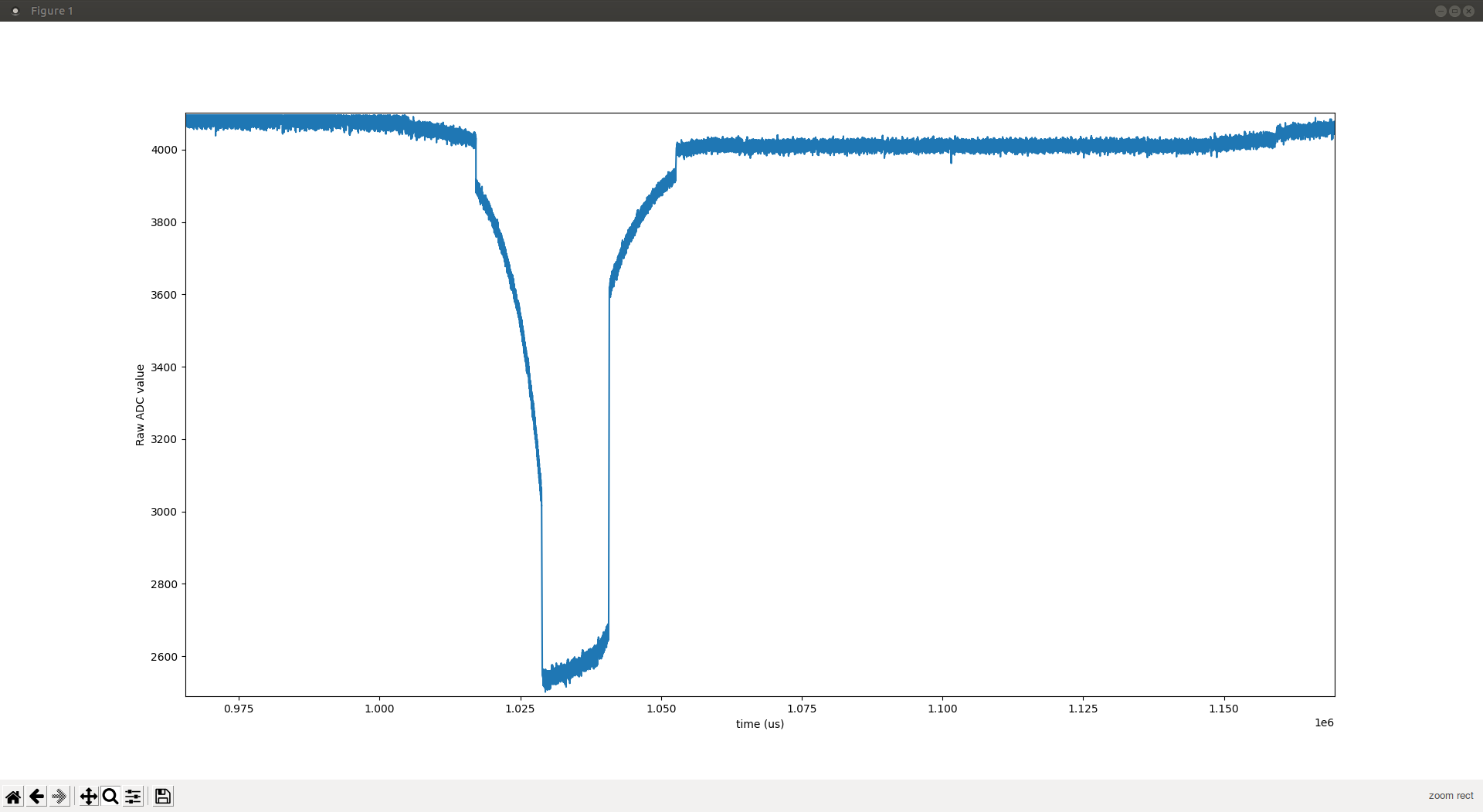
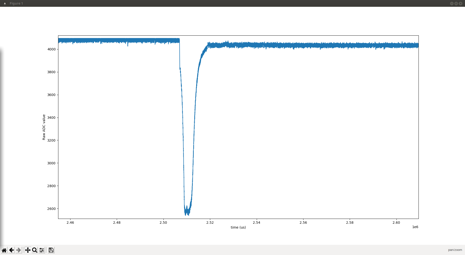
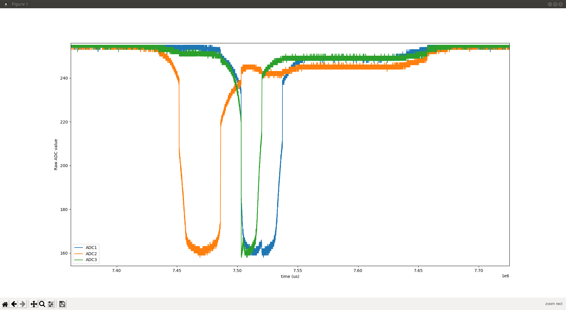
RIP In fact the ADC number is not linear with distance for three reasons:
ADC conversion (both in value and in time)
time response for the sensor
Despite it not appearing in the CNY70 data sheet, I'd expect all of the sensors will have some time delay. But, I've largely discounted it:
- They're interested in transitions from light-to-dark and vice versa, for barcode reading, and such. (Maybe even PWM'ing the LED.) So in those cases, the phototransistor has to charge, or discharge, "completely". We're interested in smooth and continuous motion with an always-on LED, and it takes place on "longish" timescales.
- Note in the 'RCA6 data sheet that the times are a function of load resistance in their example circuit. That example circuit is what CyberGene used, and you're using, but not what I'm using. By hooking a transimpedance amplifier up to the output of the phototransistor, you show it a frequency-dependent load resistance. At the <=20kHz frequencies I'm dealing with, that load resistance is ~0. (It is technically a function of the gain-bandwidth product of the op amp you use.)
I believe any time delay can be safely written off as sub-microsecond when using a TIA.
RIP current from the sensor (ADC measures voltage but V=RI is quite linear)
Alas, the phototransistor is not an ideal current source, and V=RI is not the end of the story. If you look at figure 6 of the CNY70 data sheet, you see that the output current not only varies with the forward current of the IR LED, but also with the collector-emitter voltage. By just putting a resistor above/below the phototransistor and applying a constant voltage, the Vce voltage will vary. With no light shining in, and no current flowing, the resistor will drop 0V, and Vce will be the entire voltage of the supply. But as light shines in, and current flows through the phototransistor, the resistor will begin to drop voltage, and Vce will drop.
The TIA, again, shows the phototransistor a constant Vce. I set that voltage to 1.3V, which was a convenient value to hold stable.
I may have written this better/differently on my CNY70 notes page. https://github.com/jkominek/piano-conversion/wiki/CNY70
RIP Here is the datasheet and the relevant data is in fig. 39 at pag 171 and fig 91 at pag 284. @JayKominek may chime in with more details, since I did not dig too deeply into these 356 pages (less than the other datasheet, but denser…)
That's just the data sheet for the STM32H743; there's also a 3319 page reference manual. I'd consider the RP2040 data sheet to be combination data sheet, and reference manual.
While I'm writing, I'll note that I successfully got my hardware sampling at 20kHz, by making use of the non-uniform memory architecture of the part, and finally working out how to get the 3 ADCs to sample out of phase from each other. Unfortunately going much past 20kHz begins to show some severe ADC issues. It's possible they'd be resolvable, and the ADCs could be driven up to 30kHz, but at that point I'm also constrained enough on clock cycles that the current code can't run without dropping/ignoring samples. That might also be solvable, with significantly tighter code, and removing the convenient abstraction layer library. I don't want to bother with that unless/until the entire system is proven to work.