Skip to content

A DIY hybrid piano without ADCs (purely digital sensors)

DavisB

Latest arrival...
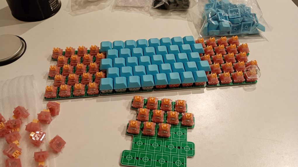
Isn't that just a keyboard?
Yes, it uses off-the-shelf Mechanical Keyboard parts (Magnetic Silent Switches (so spring + moving magnet) and standard Keycaps. But it isn't a keyboard!

It's an Isomorphic Velocity Sensitive MIDI controller!
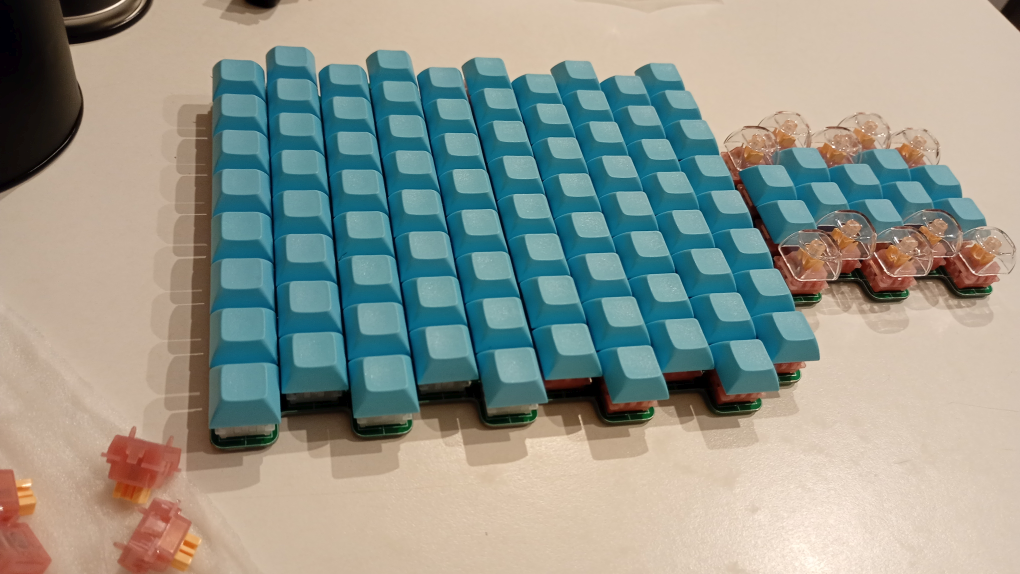
I'm always been curious about isomorphic instruments, they have always seemed like a gimmick, but I've always wanted to try one (including Jankos).

I doubt the velocity sensitivity will be good enough for playing piano music expressively, but maybe this would work as a fun synth with after touch?

I suppose this rides and dies on whether the velocity sensitivity will be "good", and there's just no way to tell without doing an experiment!

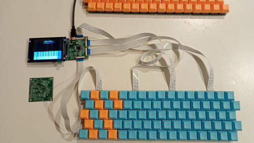
Hall Effect sensors are to be soldered on the other side of the PCB (it also has the footprints for USB/MCU, so each one of the pcbs can be a macropad/velocity sensitive MIDI USB device) and they are compatible with FFC cable pinout I use for Piano Mainboard (the analog sensor version) for traditional 88key piano.

Full size Isomorphic instruments like Lumatone use whopping 280 buttons, so almost 2.8x amount seen in the pic, but 100 buttons will do for an experiment!
Star_catcher

Hi DavisB,

I hope you’re doing well!

I’ve been following your work on the forums and really admire your expertise in hardware design and high-speed MCU implementations. I'm looking to design an economic, high-performance PCB system to scan piano keys in modular groups of 12.

Based on my initial research, I’m planning to use MagnTek’s MT8901AT dual-latch Hall effect sensors paired with a WCH CH569 microcontroller to handle the high-speed processing.

I’d love to hear your thoughts on this approach.

Thanks so much for your time and all your contributions to the community.


DavisB

CH569W is 6.2eur at 10qty from LCSC.

It has gigabit ethernet and USB3.0 PHY, which explains the price, but why would that be necessary for USB-MIDI over MCU with integrated USB2.0 PHY? Other than various hi-speed peripherals, this MCU itself isn't particularly powerful for the price. What's the rationale here?

Keep in mind that CH569 is not on (https://github.com/hathach/tinyusb) supported MCUs list, which means you'd be on your own implementing USB-MIDI. Unless you plan to do that, I'd stick with devices on that list.

Some notable cost-efficient MCUs with integrated USB2.0 PHY (480mbit theoretical max) and tinyusb support are:

  1. CH32V305 (1-2eur in small quantities)
  2. AT32F405 (1.5-2eur in small quantities, 100kb sram)
  3. NXP MIMXRT1011 (500mhz cortex m7, 128kb sram, requires external QSPI flash for code(!!!), 2-3eur in small quantities)

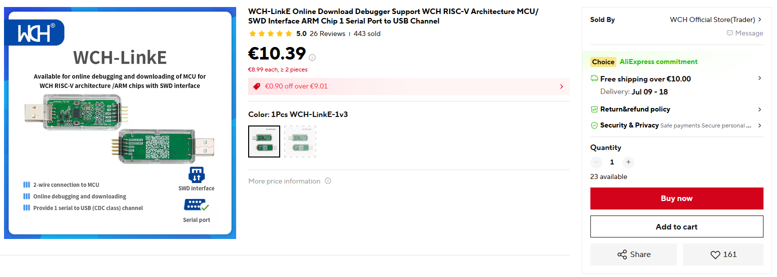
Another thing to note is that, WCH MCUs require a special SWD probe called WCH-LinkE, so you can't leverage existing probes you'd use for stm32 and various other arm-cortex based MCU.


WCH-LinkE used to go for 4-5eur a while back, but now after the newly introduced EU tariffs it costs more like 10eur (post tariff, price of of every little thing has been bumped for at minimum 4eur)

Another thing to keep in mind regarding USB2.0 HS is that you need impedance control for the differential pair (Zdiff = 90ohm). So unlike USB FS (where you can be very sloppy), you'll have to carefully calculate trace width and trace spacing as well as spacing to copper pour (especially on 2layer pcb), etc.

The difference between USB FS and USB HS (2.0) MIDI latency is somewhere around 1ms. It's not large enought to be a dealbreaker for the initial version, in my opinion.

So you can draw the MainBoard PCB for some USB1.1FS MCU (some widely available rp2040/rp2350 devboard) and then eventually upgrade to mcu with usb 2.0 when the rest of the system is ready.

I can't comment on MagnTek’s MT8901AT, it looks like something that would be used as rotary encoder for motors, etc. Not sure how exactly you're planning to use it for velocity sensing - although I highly suspect (due to how it's worded) that I'm replying to an LLMed post. 🙂


PASHKULI

DavisB I doubt the velocity sensitivity will be good enough for playing piano music expressively, but maybe this would work as a fun synth with after touch?

Not even close. More suitable to organ type of playing. Not sure what the travel Z distance of these keys (buttons) is but would assume is about 5 mm (max) which is insufficient for proper dynamics (velocity) for either organ\piano type of dynamics.

After‑touch? Yes. But it is an overkill with so many buttons. If you manage to assign and set them up for 'pitch bend up' that would be great.

It is a bit disappointing that such so called isomorphic keyboards are mostly used for microtonal layouts, which makes sense as they are not bound to full lever\parallel mechanics. The typical computer keyboard caps though are not ideal. But I advocate for dome shapes anyway.

What will be the controller chip\board used though?


Star_catcher

DavisB Fair points, thanks for your time. USB 3.0 specs has 10 times lower latency than USB 2.0. If software compatible chip exists, that would nearly eliminate the system overall latency.

Is there any mcu can be used as magnetic sensors that has built-in velocity and direction functions for greater simplicity and reliablity over time than current optical solution?


DavisB

Star_catcher

That would only eliminate USB-MIDI latency, overall system latency would still be largely dominated by VST/Audio interface/Drivers.

If your total audio latency is 5ms (which is pretty darn good):

  • USB1.1 would give total system latency of 6ms+.
  • USB2.0 would give you 5.1ms+.
  • And USB3.x might give you 5.01ms+.

So USB3.x over USB2.0 would likely give you somewhere around 2% improvement in total end-to-end latency. (ideally you'd accurately measure it if and when attempting to make such improvements)

USB2.0 is where you reach diminishing returns point, going above that drives up price and complexity significantly for minimal gain.

Hall effects / TMR sensors with analog output aren't all that different from reflective analog out optical phototransistors in terms of complexity. (other than usually being bipolar, they hang in the middle of Vdd and go up or down depending on the polarity of the magnet)

Although there are many kids of magnetic sensors, like thousands of different models with different sensitivity, min max ranges, some output PWM, clocked data out, etc. TMRs being the highend significantly pricier option.

One of the reasons I stayed away from magnetic sensors thus far is crosstalk - my piano sensors for 5.2" octave are mere 11mm away from each other, and unlike optical sensors - I don't know any simple or cheap way to provide shielding from magnetic crosstalk.

The magnetic keyboard switches are more like 19mm center-to-center distance, far enough from each other for no notable crosstalk to be observed.

Alleged reliability issues of optical sensors are mostly overblown by people who have no personal experience with them.

I'm still sticking with optical sensors for my Narrowkey Piano Actions, magnetic sensors is for experimental stuff for now.

Don't take my word for it, conduct experiment(s) and measure everything (including end-to-end latency). And report results 🙂


Star_catcher

DavisB Totally agree with your measure of system latency. My audio interface with an old Mac on linux is approximately 2.5ms with an opensource cli sfz player, which means reducing 1ms is meaningful theoretically.

In my view, optical sensor crosstalk problem with the environment around the action would be incovenient for some. For example, other light sources. Magnetic sensor is tiny chip and only measure a very close distance with neodimyum pinpoint or plate.

Looking at some SMT sensors, I find that some have built-in digital velocity and direction measurement which built exactly for need of mechanical industries. So, optical solution requires a far more complexity software management. Would it possible to make another experiment?

I am not an expert in the field of building embeded system like you. I am glad to have the conversation. Very helpful.


DavisB

Star_catcher

Looking at some SMT sensors, I find that some have built-in digital velocity and direction measurement which built exactly for need of mechanical industries.

Can you name the list of exact model numbers for the sensors that have built-in digital velocity and direction measurement - so that I can take a look at them?


DavisB

Do you mean dual-latch sensors with the fixed 1.45mm distance between hall-effect sensing elements?
You're right, these perhaps could be used somewhat similarly to optical slit sensors - namely magnet doesn't move towards and back from them (as in distance measurement), but along them thus triggering the hall effects one-after another.

As long as you can make the 1.45mm trigger distance correlate to correct points on the keydip (this is kind of like 2-sensor action), this could work.

However, make no mistake - these sensors don't have any embedded smarts to measure velocity/speed, they are for magnetic rotary encoders, mainly measuring motor rpms/direction, that kind of thing.

(with optical slit sensors and a encoder pattern you can have multiple trigger points though and the trigger distance can be changed, etc)

That being said, these might be worth doing an experiment with...


Star_catcher

I found some videos of building magnetic sensors for key detection. I am not sure how he implemented the solution, but it seems working.


DavisB

Star_catcher

Just regular off-the-shelf hall-effect sensors with analog out and cd4051(8chan) or (cd4067 16chan) mux fed into ADC of Arduino Leonardo, velocity is derived from delta T of crossing two threshold values.

I urge people to conduct experiments.

People tend to make up all sorts of ideas in their head about all sorts of "problems", of what's simple or complicated, of what will work and what won't, of what's easy or hard to do, or not.

And these ideas don't come from the Praxis, from the Experiment, but from mere concoctions of the mind -
never challenged by the Experiment.


Star_catcher

DavisB If the video indicates that magnet sensor works, does digital hall effect sensors that directly return velocity and directions can be used instead for minimal software mantainance and system complexity.

A few sensors I looked at: TLE5012B, TMAG527, AS5047P, ATS19520


DavisB

Star_catcher

TMAG5273 is a low-power linear 3D Hall-effect sensor with I²C interface.
Have you ever talked to 88x I2C devices at once over a span of roughly 1meter at the bare-minimum necessary 10ksps per sensor sample rate? Incl. but not limited to converting the 3d position(s) to velocity?

If not, where does your ideas about "minimal software maintenance" and "minimal system complexity" come from? LLM? 🙂

P.S. This conversation is over. Make a seperate thread.


DavisB

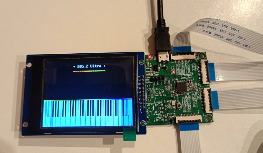
DB5.2 Ultra
The minimalist cheapest cost-optimized mid-range MIDI-controller for analog sensor systems.

  • Perfect 20 kHz scanning rate
  • Up to 96 keys (each FFC connector is up to 24 keys each)
  • Real time display of all 96 sensor readings at strict 48 frames per second (with perfect frame pacing)
  • USB 1.1 MIDI with no added latency (apart from USB 1.1 1ms).
  • Works with both hall effect sensors, reflective optical phototransistors, etc.

Single STM32G474. 5x ADCs (all used!). 128 KBs of total SRAM (currently ~ 70 KBs used, and 58 KBs free SRAM). Flash use 31 KBs (481 KBs of free flash).

Still plenty of unused computational resources left on the table. For example, it can handle 30 kHz scanning rate also, BUT it is entirely bottlenecked by analog value setting time after hc4051 mux switches.

(experimental isomorphic instrument, here only 80keys, 20 per cable, hall-effect), multiple of these boards can be chained into main board (isomorphic instruments like this require lots of keys usually as they are duplicated).

But this also works perfectly for traditional digital pianos (after all the principles are all the same).

AI use disclaimer: this product uses zero LLM generated code or outputs of any kind


DavisB

There's one aspect of this that kind of completely blew my mind.
Namely, that a single 170mhz Arm Cortex M4 of STM32G474 can render all 96 graphs on a 320x200x16bits per pixel screen at 48 frames per second, rerendering the whole screen every frame (6 megabytes per second of bandwidth just updating the screen).

While at the same time scanning all the 96 sensors at 20kHz (using 5 ADCs) AND handling USB MIDI events at the same time. While adding strictly speaking almost no latency whatsoever (microseconds at worst).


I didn't think this would be possible, but with a little bit of careful programming, it is!

Since each sensor is 20000 samples per second, and screen is 320pixels wide and updated at 48fps, you get to see 15360 of those samples in real time 🙂

This is what most of SRAM is used for 96sensors x 320samples x 2bytes per sample = 61.44 KB sample history memory


DavisB

Some other tidbits:

  1. These FFC cables can be bought in all sorts of sizes in 600mm and up to 1 meter in length (these sizes however, are way less common and tricker to source). Important for 5.5" and 6.0" octave pianos.
  2. The board is tiny 4layer 50mm x 50mm, and the board is drawn in a rather obsessive manner to avoid anything digital coupling into analog side. For example, on FFC between every analog signal, there's a ground wires on both sides, etc. And the overall analog signal is very, very quiet.
  3. Most noise in the readings in the isomorphic instrument version here comes from dirt cheap chopper-stabilized hall effect sensors (this helps with temperature drift, and zero-offset variability in hall-effect sensors, needless to say, there are better hall-effect sensors on the market). So the noise doesn't come from the main board ADC (which is dead quiet in comparison)


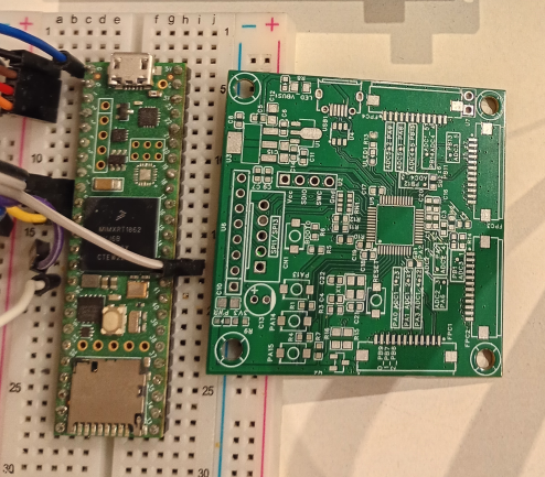
The board next to my old dusty Teensy 4.1 (which I don't like using, because it's way too expensive, too powerful, has some weird bootloader/DRM and using it with Arduino HAL is throwing away 90-95% of performance of the thing anyway 🙂)


DavisB

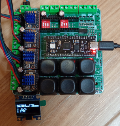
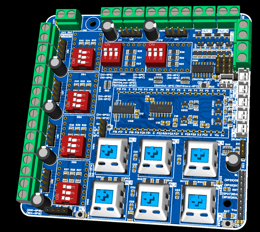
Newest "product":
Piano Factory Control Board

  • Up to 6 stepper motors (12V-24V)
  • 4 mosfets (for inductive loads, controling solenoids, relays, and vacuum pump DC motor, etc, up to 24V 3A if I recall)
  • 5 inputs (endswitches, etc)
  • Control via USB or UART
  • I2C OLED or SPI screen connector (I2C will be used for pressure sensor)
  • 6 large keyboard mech switches for user control.
  • rp2040 devboard as main MCU.

For automatic measurement, calibration, assembly tasks, etc.
A more sane approach is to leverage existing 3d printer mobo for this, instead of DIYing, but... where's the fun in that. 🙂

The only woopsie I did with this is that GRBLhal rp2040 core expects slightly different step/dir pin arrangement to what I'm using here (it's an easy fix, but for easier GRBLHal porting requires reordering another pcb rev). Outside of that it works perfectly 🙂


scherbakov.​al

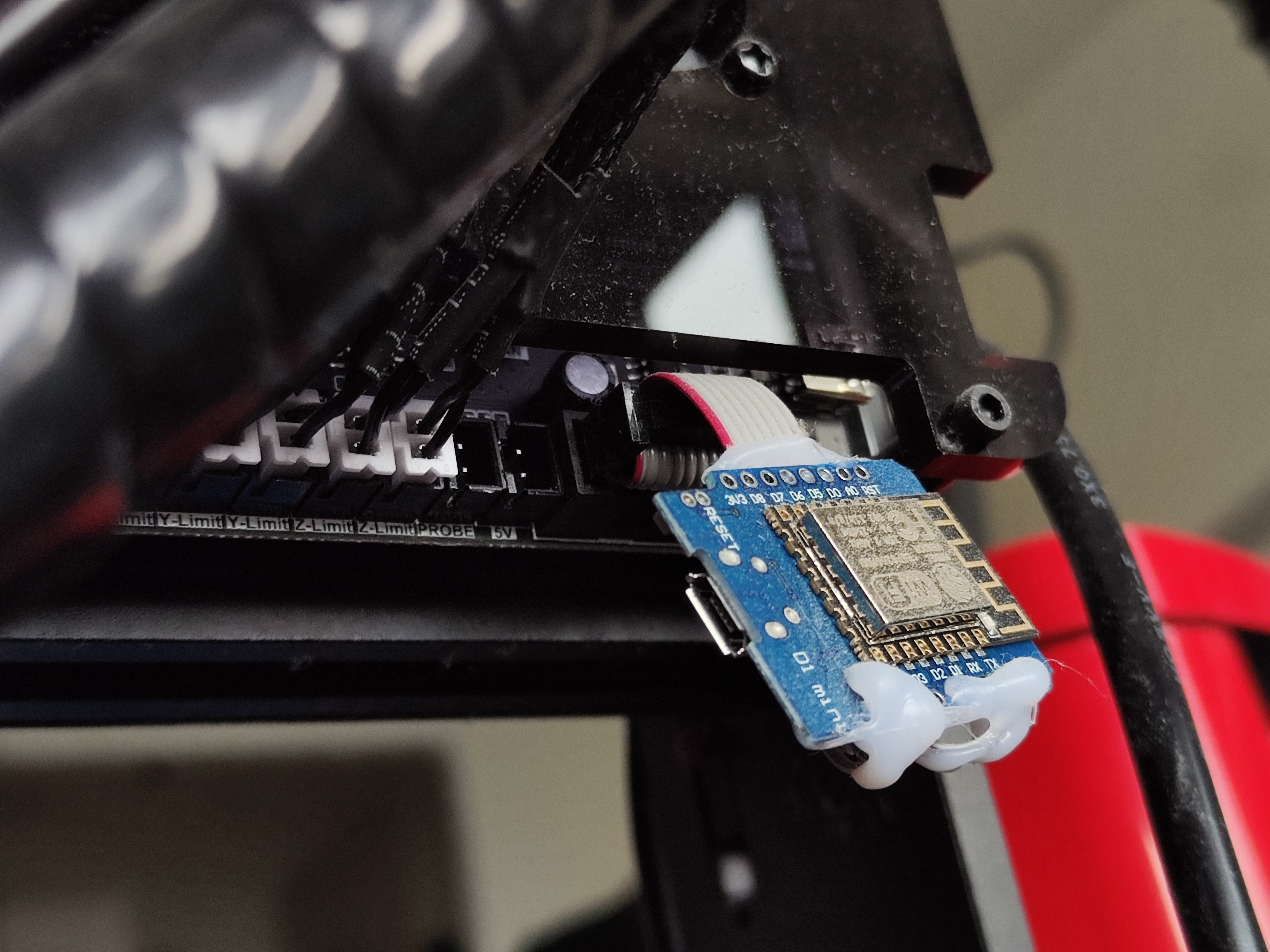
I once added Wi-Fi control to my CNC machine. It’s actually quite convenient when paired with a lightweight wireless keyboard.


DavisB

Yes, various esp32s work great as wireless UART bridges and such.
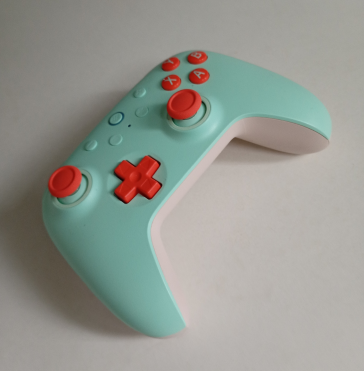
I use this bluetooth gamepad for remote control of CNCs:

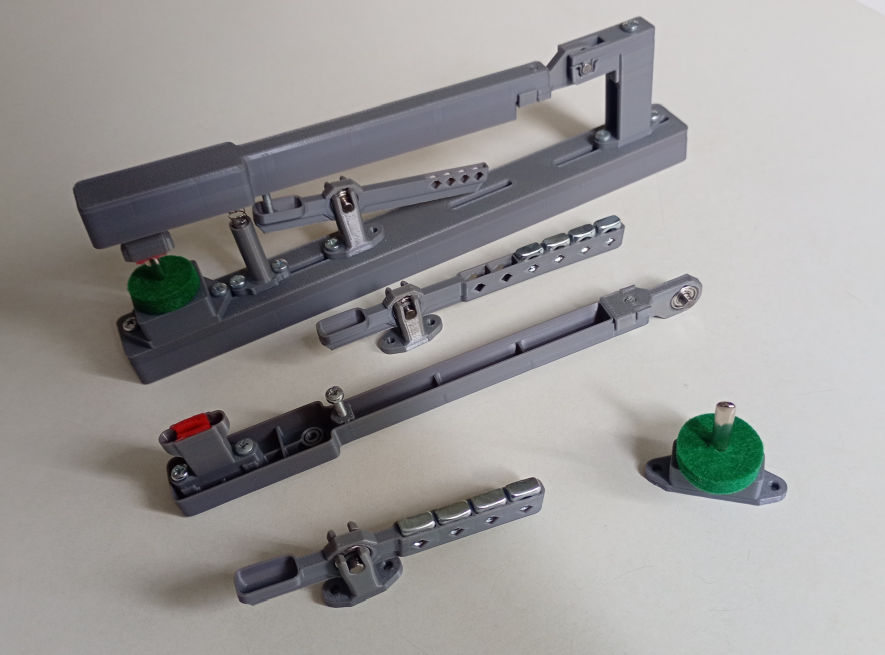
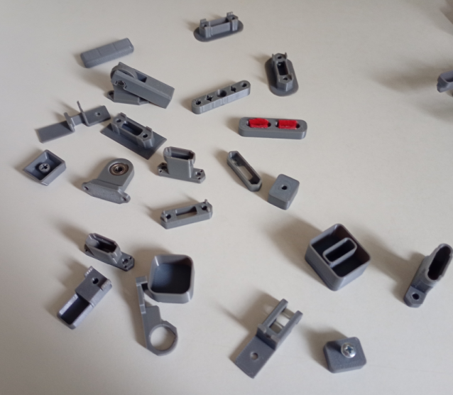
Feasibility testing & experiments of 3d printing various NarrowKey piano parts.
Currently short pivot folding types and related parts.

Its so much fun!
All these tiny parts with these tiny intricate details. Tiny weighted hammers, etc.

Is 3D printing a "good feeling"narrowkeys feasible? I don't know yet, but so far I haven't run into any problems (except for 3d printing being inherently very slow process... but that "problem" has a very boring solution 🙂).

There's something very satisfying about making these little tiny test pieces (and I'm learning), like lego / meccano pieces you screw together and customize - what happens if I add a spring to the action, what happens if I move it a little bit there - how does that change the overall feel of the action, etc.


DavisB


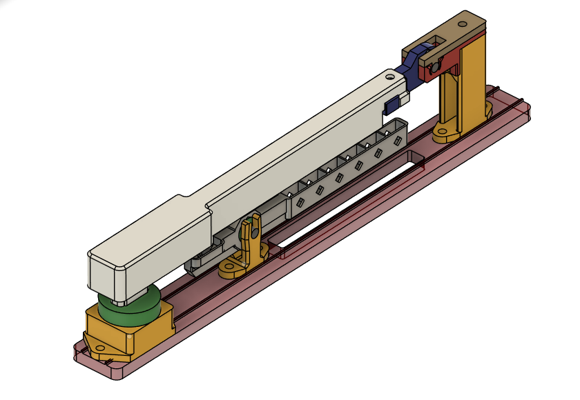
The white part here is roughly 10gs of PLA, and takes roughly 25mins to print on Bambulab A1.
For a whole set of 88 keys - roughly speaking - 25mins x 88keys = 2200mins = 36.7 hours of nonstop printing.

It appears that the fancier printers (H series, X series etc) don't actually move the needle that much, usually somewhere around 20% speed improvement. But for this particular piece - it takes 25mins down to 22mins (changing printer from A1 to H2S/H2D or X2D in Bambulab Studio on same quality settings). 36.7->32.2 hours or so.

There's some other tweaks, like changing nozzle from 0.4mm -> 0.6mm and such, but they are still relatively marginal improvement.

The boring solution is that the printing speed (throughput) scales linearly with numbers of printers.
So 1x A1 (250eur) to 4x A1 (1000eur) brings down printing time 36.7hours -> 9.16hours.

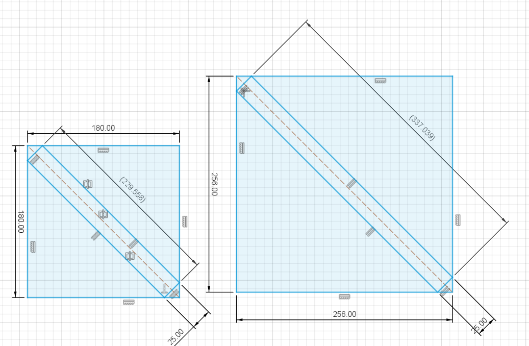
The prototype here has a pivot length of 178mm. Pivot length of Kawai MP11 is 240mm. So large pivot key does fit on a print bed of 256x256mm area printers (A1, P1S, P2S, X2D) without printing on the diagonal.


Max size if printing on the diagonal (the 180mm plate is A1 mini).

That's why print farms generally speaking - spam A1(250eur) and P1S(370eur) - they are cost efficient - and reasonably reliable - hands-off fire & forget type of printers.

If it turns out that ASA/ABS (or other fancier engineering materials) is an absolute necessity, X2D seems like the perfect fit - dual nozzle, heated chamber (important for consistent prints), better air filtration system, and will print pretty much any material you throw at it and just 630eur. Getting 4x multiples of a pricier printer is admittedly less fun.

P1S can also print ASA/ABS, but without heated chamber getting consistent prints is probably significantly tricker and more involved process?


« Previous Page Next Page »