Skip to content

A DIY hybrid piano without ADCs (purely digital sensors)

DavisB

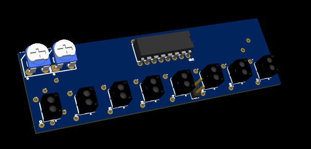
I've made a hc238 muxing circuit using just through-hole components for purely testing purposes since it easy to attach oscilloscope and see if solder joints are OK. And this time it works as intended!

(trims are there for testing purposes only so i dont have to resolder resistors)
However there are still issues with sensors impacting each others readings. For example if one sensor is reflecting, you get max value 4096, and if all sensors are reflecting, you get only around 3500 as max value, or sensors next to each other. Which isn't optical crosstalk as far as I can tell!

So this kind of muxing probably works just fine as-is for slit sensors, but for purely analog sensors it needs some improvements (such as only blinking leds via hc238 to reduce power consumption and still use analog mux for constantly powered phototransistors?)

The good news is that I've made all the software side on stm32 take zero CPU cycles to do ADC conversions and muxing.
PWM timer with 160khz frequency, 1.25us low (for the transition), 5us high - all easily adjustable.

Every 6.25us timer triggers DMA transfer a bitpattern on relevant GPIO pins (memory to peripheral DMA transfer to BSRR - Bit Set Reset Register)
On the rising edge of 5us high initiates automatic ADC conversion (after the 1.25us transition settling time)
ADC conversion automatically outputs results via another DMA channel out into a result buffer and moves to the next position in a circular buffer.

This uses no interrupts, and effectively no cpu cycles!

You get automatically filled buffers with sensor positions all the time with zero CPU involvement! Sampled at the exact muxing timings I specify!
This happens fully automatically in the background all the time.

What's beautiful about this is that it has the exactly same code and hardware pinouts when muxing using analog switch cd4051 or muxing using hc238!
I took my old PCB that uses analog switches plugged it in - and it just works! Same code & same hardware interface!
All 8 sensors beautifully streamed via UART (up to 5.7ksps each via 921kbit uart)!

Might be a good idea to add another ping-pong DMA buffer (like double buffering)...?! software side really is the easy part with debugger where you can add memory and variable watches and see buffers, periperals and their data changing in real time!

Another cool feature of stm32g4 is VREFBUF (with available values for VREF being 2V, 2.5V, 2.9V). This also works wonderfully.
Built in OPAMP follower also seems to work great. (havented tested built in programmable gain opamp yet!)

If muxing/adc sampling can be made like this to take zero cycles, it feels almost as if single measly stm32g431 (arm32 cortex m4 @ 170mhz) might just be fully sufficient for a full piano...?
DavisB


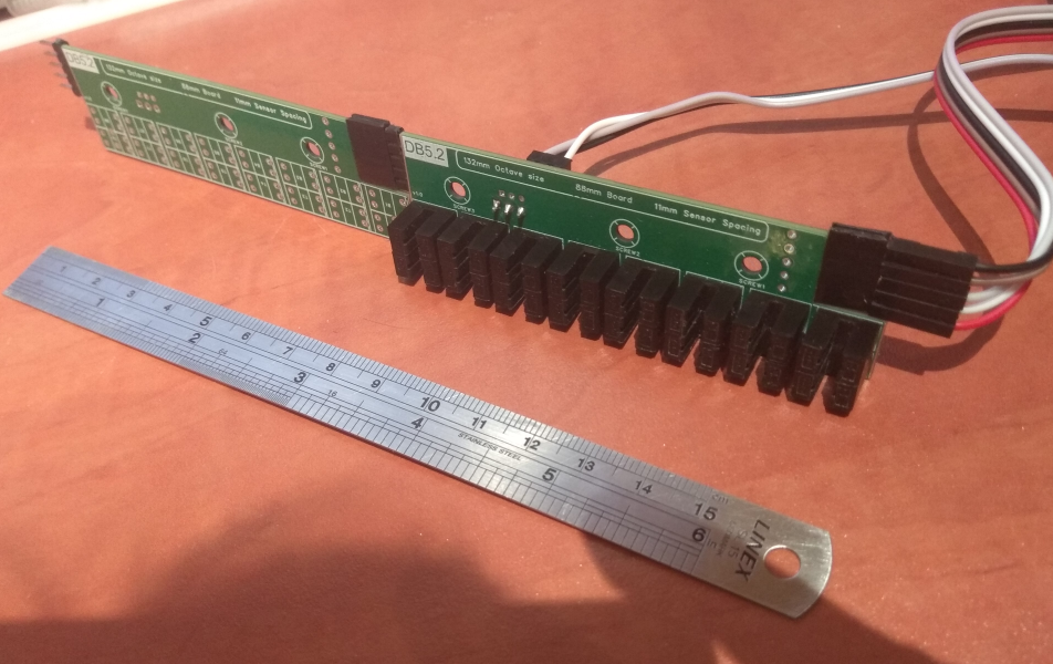
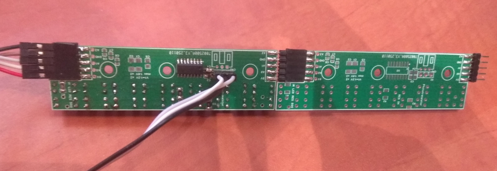
Pcbs from JLCPCB came for the hc238 muxed slit version. Seems to work as expected at 20khz per sensor at the moment!
Components per board - 2*8sensors (very fast and easy to solder!), 3resistors(1206), 2 decoupling caps (100nf, 1uf 0805), one sop-16 ic, lots of DNP (do not place) pads, 1.2mm fr4 2layer, one side almost unbroken ground plane (except for where the pcbs join).

Beginner hand-solder friendly (except for two 0805 caps?), the only upgrades to this design that I can think of are:

  1. Make it into 2pcbs (11mm * 44keys * 2pcbs=484mm * 2pcbs) instead of 11pcbs (of 11mm * 8keys * 11pcbs=88mm * 11pcbs)
  2. Smaller slit sensors, with smaller slit (these have massive 1mm slit where the IR light shines through).


(soldermask is incorrect, it is powered from 3.3v!

Very cost effective design, ~ 4eur (2eur boards, 2eur shipping), for 5pcbs (out of 11 total). Needs one more main board (<100x100mm) with rp2040 and that's it.


CyberGene

DavisB I considered such a design for a long time with those optical interrupt sensors. It makes everything very simple electronic-wise, basically the same as any digital piano or MIDI controller with membrane switches. But it requires careful mechanical regulation and PCB positioning, along with adding some shutters to each hammer and at the time I was afraid that would require way too difficult planning/designing/drawing for the PCB-s to follow the exact hammer footprint and position.

However, from a certain perspective, I think it’s the way to go for a mass produced piano (yeah, Kawai chose that solution, and Yamaha have a mix of this and over complicated key sensors).


DavisB

Yes, intuition tells me that analog version with ITR8307s (6-7cents a piece) can be built with lower BOM and lower labour/assembly time costs (certainly with SMD PCBA), and overall be less finicky mechanically.

Seems like those will require more than just hc238 ic for muxing.

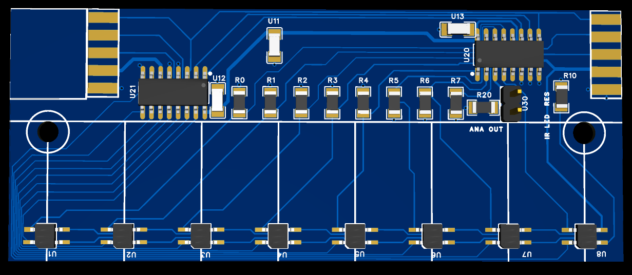
Something like this maybe:

(completely unbroken ground reference plane, some very thin traces. 1mm thin pcb two layer fr4? Still thinking whether to put a ground pour on top, so this is not a finalized design)

HC238 blinks only leds, CD4051 analog mux for phototransistor output. Phototransistors probably will be always connected and always pulled to ground via resistors (R0-R7). Or optionally they can be pulled to ground AFTER muxing via cd4051 (pulled with R20).

This design has too thin traces for me to build at home, so has to be ordered for an experiment...

Another version to try is to have everything on all the time (and mux via single CD4051) and barely-just-barely try to fit it into 500mA power budget. If it fits in 500mA (or if you don't care about exceeding 500mA a bit), this could be fairly straight forward, simple design too.... (as long as you don't get bitten by lack of analog electrical engineering background)

Comparator method is still not dead in my mind, g431 has a fast dac and a fast comparator.... which could be callibrated automatically programmatically (the threshold points, etc)....


DavisB

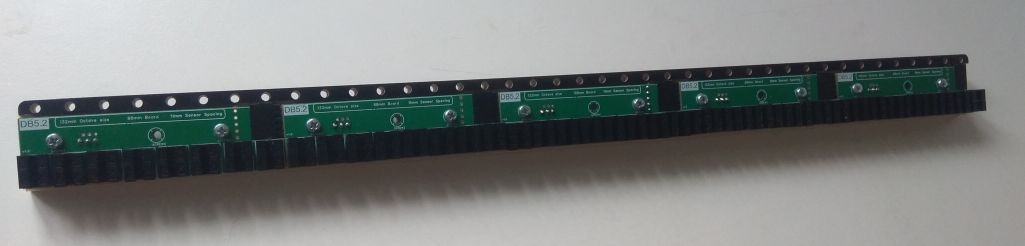
Retiring sensor strip from my old narrow key (5.2" octave) prototype:

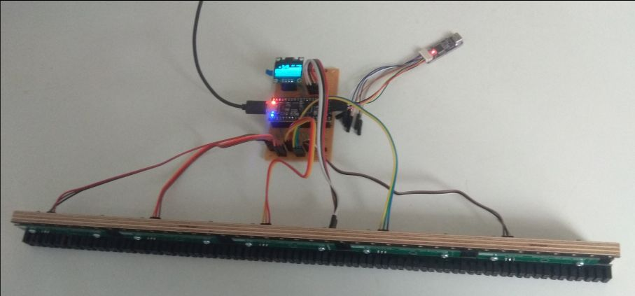
This is a strip 5pcbs * 8sensorpairs = 40 keys. (5 cables going to main pcb, the 6th one is addr+vcc+gnd). No external power supply required. Whole system runs on less than <150mA. 20khz sample rate.

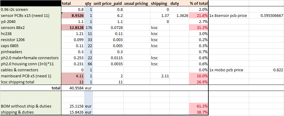
Bom cost for a whole piano if done like this (with pcbs with mainboard too, here's it's just soldered wire to wire connections on proto-board):

Single ~ 1.1eur yd rp2040 devboard sufficient for whole 88key prototype! BOM cost for the whole system is roughly 41eur all inclusive.

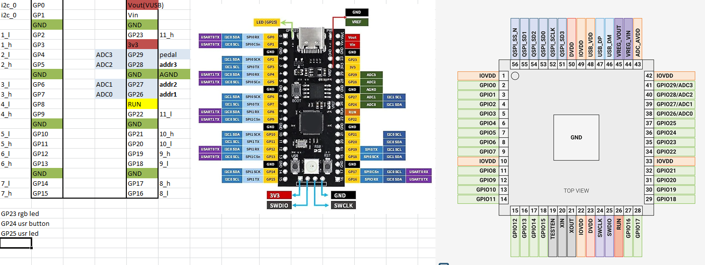
Pinout:

If using such devboard, only 1 pin is left for pedal. This design relies on scmitt-triggers in rp2040 pins (outputs of those slit-sensors are analog!). Main board PCB requires basically almost no circuitry, just direct point-to-point connections (except for address pins, series termination resistors (30-50ohm) would be recommended there.


DavisB

All wiring in this design can be completely eliminated by combining all 11pcbs * 88mm * 25mm into one 968mm* ~ 50mm PCB where you plug in yd-rp2040 without any wires required at all. (just usb-type-C into computer, and sustain pedal that's it)

Note that PCBA services usually have board size limitation of 450-500mm. So combining two large pcbs is probably the right thing to do (with some wire jumper connecting the two).

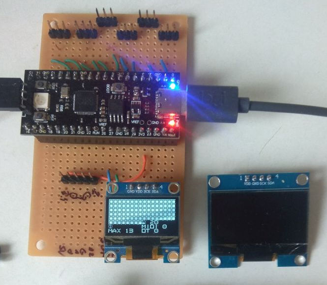
Main board has single 0.96" i2c display for debugging purposes (just shows status animations of all 88 keys and some midi events). This is less finicky than wiring up status LEDs, etc. And very cheap. Highly recommend getting 1.3" i2c displays though. Same resolution, but significantly bigger and price is only +30c +50c or so more.


DavisB

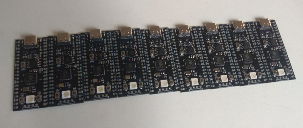
I bought ten of these yd-2040 boards, thinking that there surely must be some sort of catch, or that they use fake defective parts.
After all, they each cost around ~ 1.1eur each (including shipping)!

rp2040 is ~ 50cents in volume.

Surprisingly enough, they all work perfectly so far. Different patch sometimes uses different flash (sometimes winbond, sometimes zetta, sometimes boyamicro). These 4mbit qspi flashes are usually 8cents a piece or so. But still, it's hard to see how they make almost any money at all on these. Or maybe these are somehow defective and I haven't stepped on the defective peripheral just yet.

I suppose these don't overclock as easily as original pico board (due to use of different flash).

Design wise these are better than original RP2040 pico board, they use usb-type C, LDO instead of RT6150 buck-boost SMPS, seperate boot/rst/user button, rgb led, etc.

I also have original rp pico and weact rp2040 board, but I like these boards the best thus far.


DavisB

Software wise it's all very simple too (less than 1k loc total, with lots of comments/whitespace, and 30% of it is driving ssd1306)
20khz sampling rate gives a time window of 50us.

Scanning whole piano and adding events to a single-producer single-consumer SCSP ringbuffer takes around 3-4us (or 6us at most, depending on amount of events, etc).
This is implemented using one PIO and one PIO statemachine, 1 dma channel, and interrupt triggered 20k times a second on DMA transfer completion (whole piano scanned). Total interrupt entry-exit is around 50cycles for Arm cortex m0+. CPU ~ 6cycles to test each sensor for events.

And in the main loop, ring-buffer entries (events) are taken out one by one and sent out via USB-MIDI.
This is also where delta time gets converted to MIDI velocity (this can take considerable amount of cycles depending on how it's implemented).

There's 200kb of sram available for lookup tables. Lots of flash space for that too. And plenty of cycles fixed point log implementation, etc.

Second core is completely idle! Or rather in my implementation it drives i2c screen using DMA. So dma transfer has to be started at 30hz. Rest of the time it's idling. Lots of computational power left unused.

rp2040 has absolutely fantastic documentation and SDK, and generally speaking is very pleasant to program for.

The whole piano could be sampled at higher rate too (40khz, etc), but this is limited not by CPU time, but by phototransistor switching time due to hc238 muxing implementation.

At first I was slightly concerned that rp2040 is too weak for this task, but it is absolutely not. The only drawback is that it uses usb 1.1 /fullspeed / 12 mbps 1ms pooling time. The only drawback I can think of thus far.


DavisB

Great news! As of Pico SDK version 2.1.1 rp2040 has been certified to run at 200mhz!

RP2040 has now been certified to run at a system clock of 200Mhz when using a regulator voltage of at least 1.15 volts.

With this version of the SDK, you can now select a 200Mhz clock for RP2040 simply by setting SYS_CLK_MHZ=200 via preprocessor define. The regulator voltage will automatically be raised for you if necessary.

https://github.com/raspberrypi/pico-sdk/releases/tag/2.1.1

Easy 60% perf gain for nothing! This isn't an speculative overclock either, it's in spec now! This apparently came along with release of the new rp2350.

Seems to works perfectly on the yd-2040 boards, I also had a typo earlier, these boards come with 4mbytes of QSPI flash (32mbit) or 16mbytes of flash(128mbit). Original pico boards have 2mbytes(16mbit) of flash. Not that there's any real use for that much flash memory most of the time, certainly not in a MIDI controller.

Speaking of megabytes, Yamaha P-120 (released in 2002) had total wave rom size of just 32mbytes (for the whole instrument, includes other sounds, not just piano). Yamaha P-515 (released in 2018, 16 years later) had a total rom size of 256mbytes. Yamaha P-525 (released in 2023, 5 years later) has total rom size of..... unspecified amount (for obvious reasons)....


RIP

Thanks for the update.

DavisB Retiring sensor strip from my old narrow key

DavisB All wiring in this design can be completely eliminated by combining all 11pcbs * 88mm * 25mm into one 968mm* ~ 50mm PCB

Are you retiring the old ones to replace them with consolidated large ones? Or some other reasons? Are you still working with the slit-sensors? I never tried those myself, but I always thought that the calibration and/or tolerances would be very tough for a DIY project, so I discarded them to begin with. I'm interested to learn your experience with them, if you are willing to share.

DavisB I bought ten of these yd-2040 boards

DavisB each cost around ~ 1.1eur each (including shipping)!

Where did you buy them from?

DavisB At first I was slightly concerned that rp2040 is too weak for this task, but it is absolutely not.

Agreed, it is a very nice little chip. It does have its warts, though, for example this one. If you can stay away from such problems (and for some things I could not), it works great.

DavisB release of the new rp2350.

FWIW, for my "random" projects I switched to this new one (on the official Raspberry board)


DavisB

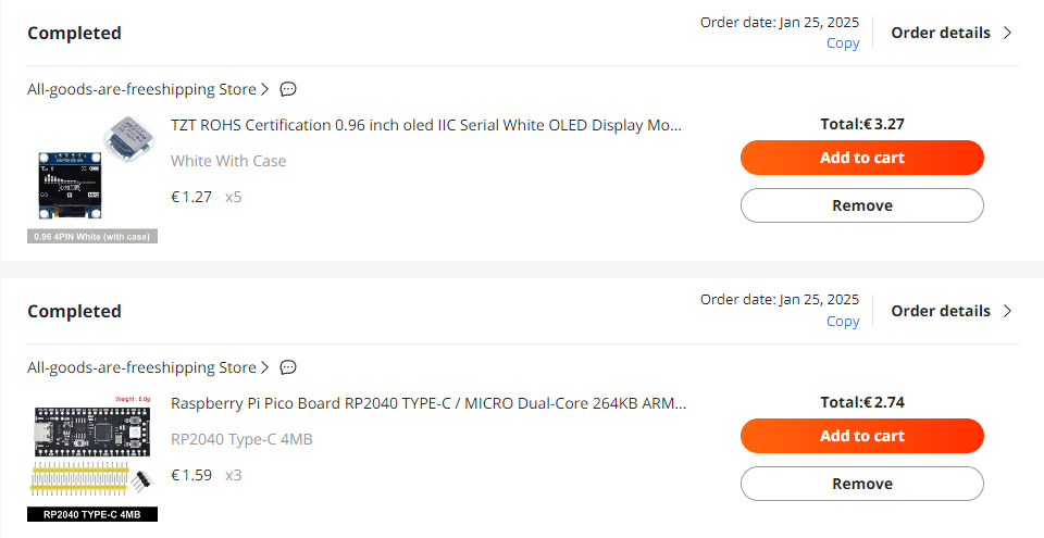
I buy these boards from AE (usually when there are major sales (ie. anniversary, blackfriday, 11.11, etc)). There's many stores that sell boards based on yd2040 design such as (https://www.tztstore.com/goods/show-6203.html ).

There are many storefronts that are operated by TZT (or use the same warehouse and sources). Prices sometimes go pretty low.

For regular people I strongly recommend sticking with more reputable sources (LCSC for parts, and for devboards & swd probes WeActStudio, etc). While everything I've ordered pretty much always works for me. Huaqiangbei markets aren't exactly like ordering from Mouser...

Random local small EMS houses make those yd2040, so different batches will have different flash, different silkscreen quality... ie. they lack the consistency and quality you'd get from WeActStudio and similar.

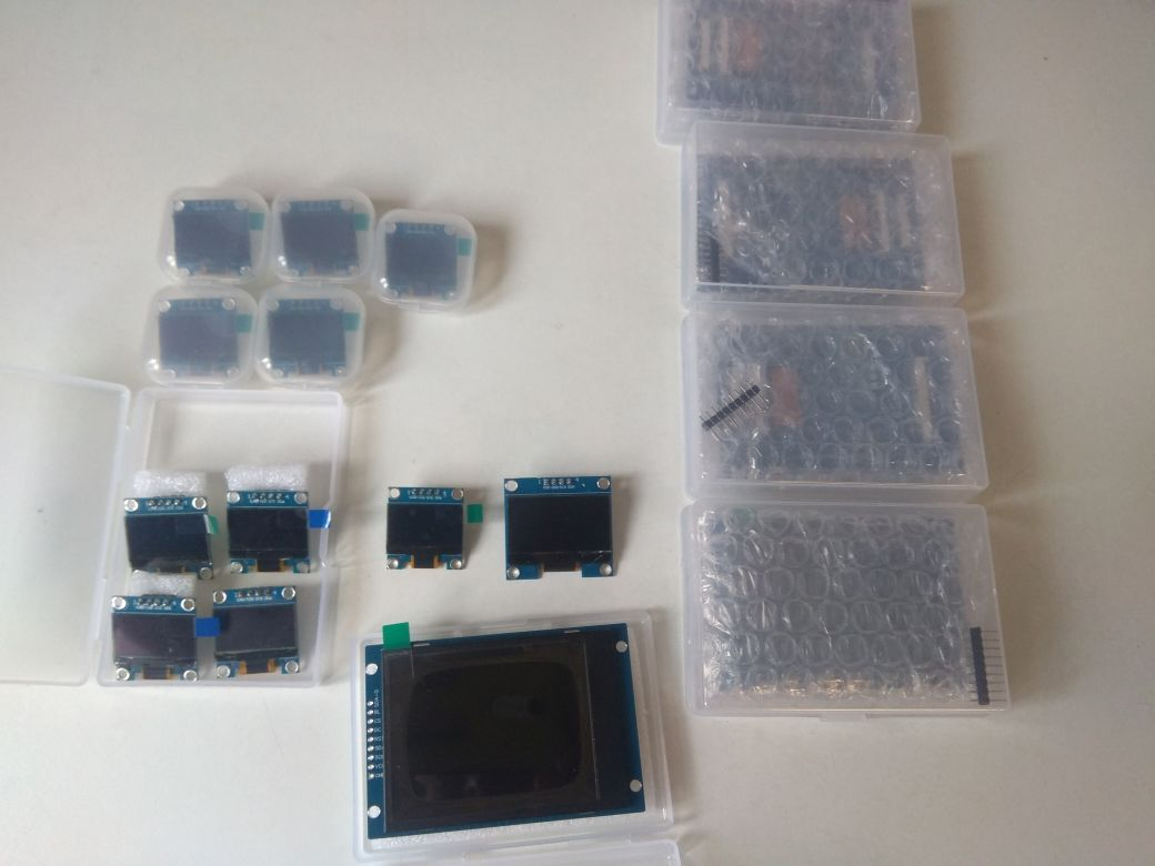
These 0.96"/1.3" inch mono OLEDs are my favorites and along with those 2.8" 240x320 ST7789V SPI color LCDs (as little €2-3 a piece on sale) I stock them and treat them like generic jelly bean parts.


DavisB

Re: I2C.

There's a comment in Pico SDK "i2c_write_blocking_internal" implementation that says the following:

A lot of things could have just happened due to the ingenious and creative design of I2C. Try to figure things out.

Emphasis mine. My understanding is that I2C is one of those deceptively "simple" things, that are best to be avoided whenever possible?

Hardware designers get it wrong. Module and I2C device designers get it wrong. SDK developers get it wrong.
The user (software developer) might get it wrong. Is it a 7 bit or 8 bit address, so does it have to be shifted or not, etc?
There are no built in timeout, the bus can hang, all sorts of stuff can happen.

If you put multiple such devices on a bus... it ends up being complicated. Even if you stick to the letter of the spec, there's no guarantee that everyone else will and well... (and then you put circuitry to just power cycle things... etc, not pretty)

There's also a version of i2c that fixes some of the issues called SMBus.

Sometimes you can't avoid I2C and there's plenty all sorts of sensor devices that offer I2C interface, etc.
And if there's just basic 1master-1slave write-only or read-only with 1device - like I2C OLED or some sensor - it's probably fine-ish, but otherwise...

Re: RP2350

There's RP2350-E9 Erratum which can only be addressed with a hardware revision. So I'll wait for quite a bit before switching over. (https://community.element14.com/products/raspberry-pi/f/forum/55046/rp2350-gpio-pull-down-latching-bug/223658)

Most issues with RP2040 are either known (the ADC issues as per errata RP2040-E11) and/or are addressed via hardware revisions (all rp2040 are on B2 I think) and well documented by this point.

Kind of like with the classic ubiquitous STM32F103.
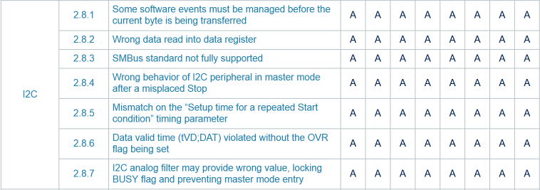
The errata is massive, here's the portion just for the i2c:


DavisB

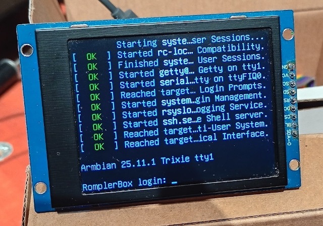
Some early experiments & evaluation of using SBCs as romplers (in this case Radxa Rock2f, around 15eur to BOM + 5-6eur microsd) and SPI st7789v screen (2 eur bom)

(using https://github.com/torvalds/linux/blob/master/drivers/staging/fbtft/fb_st7789v.c kernel driver, which exposes 320x240 framebuffer as /dev/fb0, the kernel module had to be recompilled with a slight modification to invert the colors - other than that it works well!


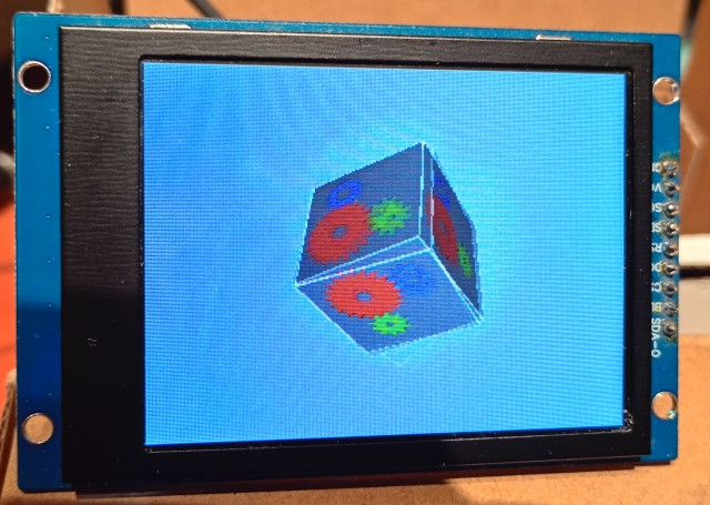
OpenGLES using hardware acceleration KMS/DRM (without requiring desktop environment, etc), the rendered scene is red using glReadPixels and sent to /dev/fb0 - which is far from optimal, but even still this simple glxgears type scene (modified kmscube) gives around 440 fps. Ie. it should be plenty good for rendering UI.


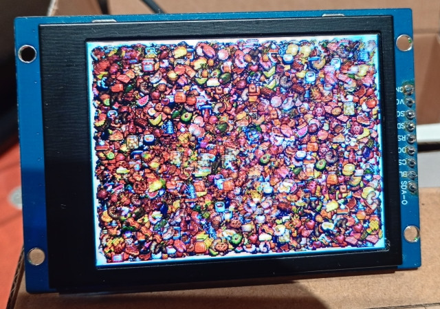
Looks like noise, but its 10000 x (size:16x16) software-rendered sprites bouncing about at stable 60fps. (one A53 core out of four utilized). My phone makes the screen look way worse than it looks in person.

Notable part is how the SoC doesn't even heat up or require a heatsink even under moderate loads at 2ghz and hangs around at 45-50C.

The crucial part of course is - whether there's a good low-level kernel API for very low latency audio, and if it can be easily attuned to this very purpose, and if Soc is powerful enough for reliably mixing 64-128 sound polyphony + convolution reverb + some basic resonance modelling in time + streaming samples from microSD into 1-2 GB of ram... (initial impressions - it absolutely should be)

Dexibell series use Arm SoCs for their instruments (and I think there were one or two other DP models that do).
I think this is the way forward as far as retail DP rompler hardware go. The Arm Cortex-A53 quadcore (Rockchip 3528) SoC is <5eur to BOM in volume (plus you need some LPDDR4).


DavisB

Apparently there's an upcoming new tariff in EU (starting from 1st of July) for small parcels which is likely going to significantly increase costs of prototyping (+3eur per item type/tax code, not package!)

So I presume this means every JLCPCB order will be +3eur tax, and if you order - say 100eur worth of components from LCSC you will pay 3eur per item type (package contains resistors +3eur, caps +3eur, connectors +3eur, MCUs +3eur, leds +3eur, ferrite beads +3eur, esd-diodes +3eur, usb connectors +3eur, etc, etc)

I really hope I'm just misunderstanding it, and this applies to neither LCSC nor JLCPCB, but I'm not sure...

Needless to say, it's a great time to build and play around with new sensorboard designs and hoard parts (LCSC has shipping discount till 30th April!), before the DIY hobbies doesn't double or triple in price. DIY hobbies, like custom DP builds and similar are super reliant on imports from China (including, but not limited to AliExpress). And they involve hundreds of different parts - many of which individually don't cost much.

Say, 500x 1% resistors in 0603 is 50cents. Or hundred USB connectors (micro USB 3eur, USB C 5eur or so), but if you tack 3eur tax on every item TYPE in a package, this would easily double and triple the total cost for things made in small volume.

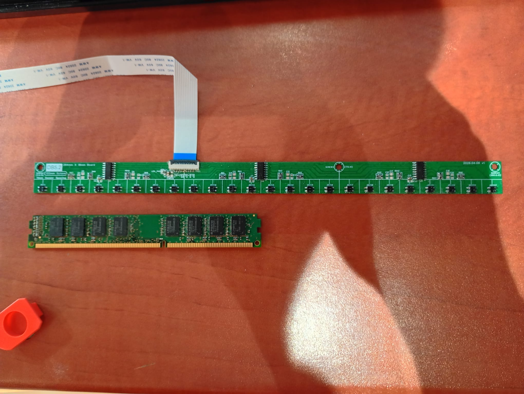
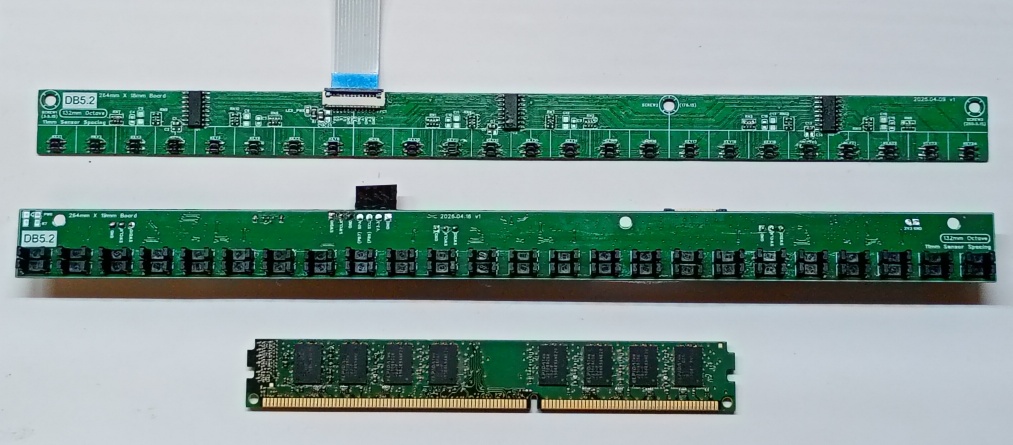
Nothing particularly interesting about this design, other than it's super tiny (1mm thin PCB, 18mm in height, compared to 19mm height of low profile ddr3 stick), uses resistor arrays and FFC cables.

4 of these boards with 4 FFC cables into main board makes for a very neat and compact system. (need to cut 1/3 of PCB off with exacto knife for the 4th board so that it's 88sensors instead of 96).

FFC cable could be much smaller (this is 1mm pitch), and has a lots of ground wires in between signals.

It has mounting holes, but the best way to mount this is using double sided tape


DavisB

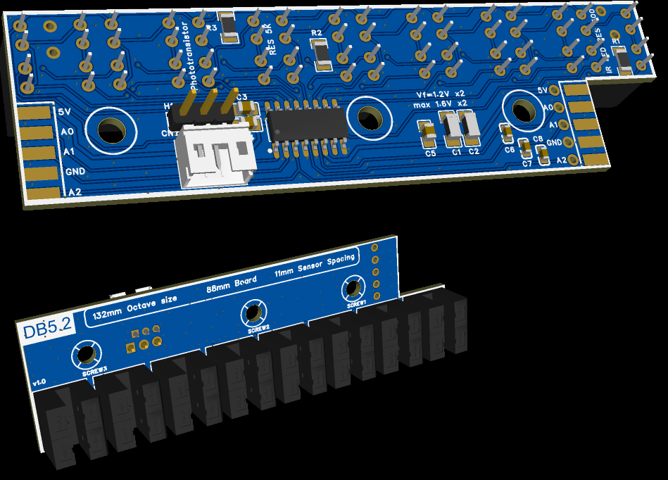
New slit board!

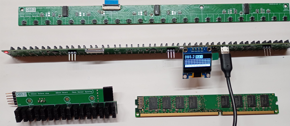
This is probably my craziest design yet. This one has no muxing or "scanning" in traditional-sense whatsoever, the board (for 24keys per PCB) has 3 dedicated MCUs each dedicated to sensing any change to any of the 8keys/16sensors and using high resolution timers to detect keypress events above 1 million times a second - which it communicates to main processor.

And all that packed into a board 19mm in height!

But that's not all - you can either chain 4 of those boards with FFC cables into main board (for full 88 key piano), or use one of these boards standalone as a 24key MIDI keyboard (it has a fourth MCU for optional MIDI via USB!), it even has a OLED screen connector (mostly for debugging and testing that all the sensors register though)

The 3 pinheaders are SWD for programming the MCUs!

Other side (those QFN mcus are tiiiny! 5x5 mm for 3 keypress event MCUs and 4x4mm for MIDI USB main mcu!):

This is probably the most high-end sports car like sensing option out there, and the only upgrade I can think of is using Vishay surface mount slitsensors (ie. vishay TCUT1600X01) and some very minor changes...

I still have a soft spot for the utmost simplicity of my previous designs, but for the very best (probably, overkill sensing resolution?), this is the best I could come up with thus far.


CyberGene

DavisB I like the idea of slit sensors, it’s simple and reliable, close to how AvantGrand and Novus work. Is it for hammers, keys, or both? What parts do you mount to the hammers/keys for it to go through the slit? I imagine this to be the tricky part but once done, it’s probably good to go for years.


DavisB

CyberGene
Just the hammers. And a machined "encoder pattern" is attached to hammers.
This thread was misleadingly named.
All the sensing systems are made for a DIY narrowkey DP/MIDI controller that uses - atleast mechanically - rather traditional DP style action.
So the hammer acts like hammers in DP actions - namely it's rather closely coupled to the key and has no real escapement. (with both all the good and bad it entails...)

The encoder patterns have to be attached at the same distance from the pivot on the hammer (or else the reported speed will be slightly different hammer-to-hammer).
Or if the cut-outs on key-element isn't made accurately it will measure the speed of the hammer at a slightly different level of keydip, etc

That's actually the main reason why I might upgrade to TCUT1600X01, both slit sensors for the key are housed into the same plastic mold, so the distance between slit1 and slit2 would be guaranteed to be even more accurate.

While these sensors do have a locating pin in the PCB, it's slightly oversized and if you're not careful you might solder them it in a way that they are not perfectly same distance from each other (at the end I started using special machined sensor holder element to ensure they get soldered in perfect alignment and positioning, etc)


DavisB

In preperation of the new EU tariffs that come into effect on 1st July:

8 different PCB designs in 2 months, covers a good chunk of ideas (including some experimental designs) I had in the back of my mind. Not seen in the pic, boxes full of components from LCSC, and all sorts of parts for future DP builds...

One more PCB design box to arrive any day now (if successful this one will upgrade Piano Mainboard from USB1.1 to USB2.0 (mcu with integrated USB2.0 PHY, theoretical max 480mbps), potentially cutting down total MIDI latency from 1ms->125 microseconds.

Details of how exactly this tariff is gonna be applied and what extra handling fees etc will be applied are unclear, but they have potential to double - if not triple - costs for small time DIY builders and hobbyists.

Before this tariff came into effect, thanks to various Chinese ecommerce platforms, you could - in effect - operate as if you're in severely time delayed Shenzhen (typical 2-3 week delivery). That's to say, you could build and source - sometimes very niche - parts for literally ANYTHING you could think of, and do that very, very cost effectively - as long as you planned ahead around the time delay on all deliveries - you could build anything.

Now every little part you order - be it a single transistor or mosfet - from China is going to be slapped with extra +3eur (per item type) + handling fees and who knows what else.


CyberGene

DavisB I’ve missed this and it might be a political issue, and I’ll move it out of this discussion in such case, but what tariffs do you mean, what’s going on? Are there EU tariffs on electronics from China?


« Previous Page Next Page »