Skip to content

DIY piano upright conversion attempt

T-Ro

I got my little proof of concept working, and I would like to jump into this community, as it is really supportive and newbie friendly. I've been lurking all the DIY projects from @CyberGene , @gzpiano, @JayKominek, @RIP, thought I would join in on the fun.

Let's jump into my setup. I'm using a teensy 4.1 with lm393 comparators and CNY70s. The idea is to use 2 cny70s one for hammer tracking one for damper.

I've got the code to work with interrupts, but I have no idea what I'm going to do to connect multiple teensy boards. I can get 15 keys to work per teensy(6 being needed), but I want to use one teensy and 16 MCP23017s(digital Io expander), with interrupts, to get this to all work on the cheap.

Code;

Video;

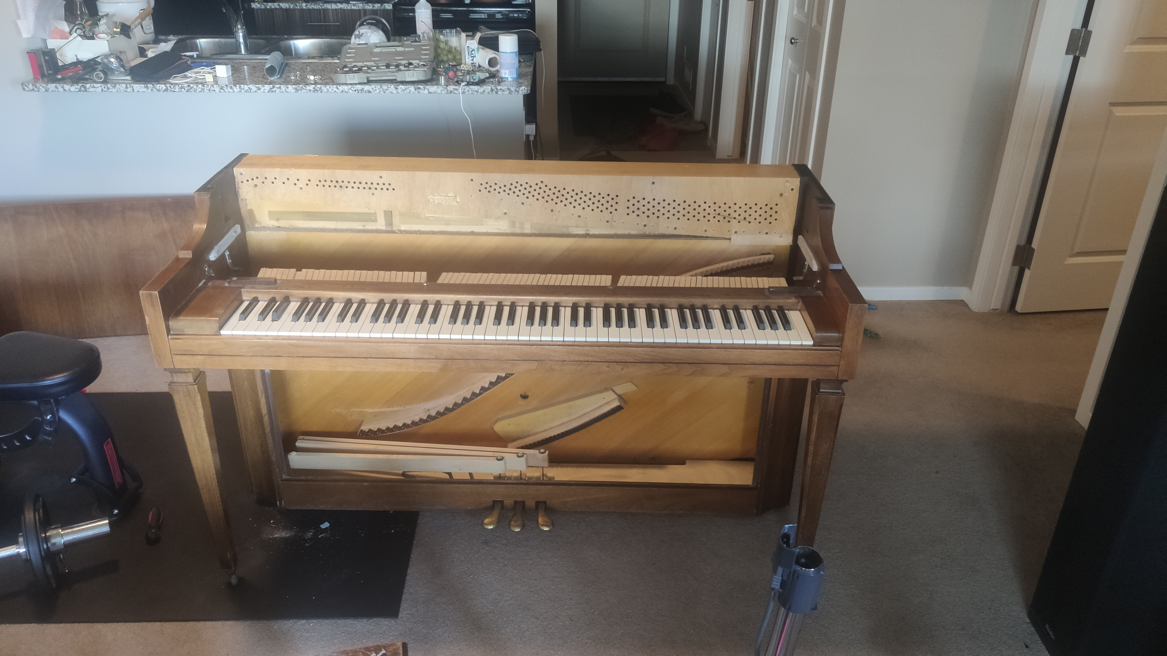
I bought an upright piano to marry this contraption to, but I need to think of a pcb design to take this further. I'm doing all of this with zero coding experience and zero pcb design experience, so this is going to take alot of banging my head against the wall. We will see where this project goes I guess!

What I'm going to work on alongside the pcb design, is using the mcp23017 digital Io expander. It's theoretically possible to get 16 of these working on one teensy board, and have 256 digital inputs with interrupts. Here is what I've found that could help.

https://forum.pjrc.com/threads/68716-Teensy-4-1-MCP23017-examples

https://www.best-microcontroller-projects.com/mcp23017-interrupt.html


JayKominek

You might consider using the MCP23S17 instead, so that you can get SPI communications to your parts. The max speed will be much faster, there's less bus overhead, and you'll be less prone to having weirdness from the number of devices on the bus. You also won't have to worry about what the right pullup resistor values are for your design, as the IO expanders will just drive MISO directly. That said, with a SPI bus you'll need to keep all of the expanders physically "very" close to the Teensy. All on the same carrier board that you're attaching the Teensy to, certainly. Whereas I2C you could run over shortish, cheap cables.

Good to see that you're already aiming to write interrupt-driven firmware, and planning to make use of the interrupt lines from the IO expanders. Just make sure to pay attention to how you capture the time(s) the interrupts trigger.

If you bring any schematics or board layouts to my attention I'll be happy to give them a quick review.


CyberGene

T-Ro welcome to our forum, nice to see yet another DIY project 👏🏻 I also had zero knowledge about electronics and PCB design which is why it was very interesting for me to learn something new. And I’m a high-level programmer with Java, so my coding experience with controllers and low-level programming was also kind of zero, so I came from the same place as you 🙂 Looking forward to your updates 👍🏻


T-Ro

Thanks for the quick replies! JayKominek thanks for the advice, that was really helpful. I have picked up some mcp23017 and mcp23s08 to try and figure these things out. The mcp23s17 is unfortunately out of stock here in Canada. Programming these things with interrupts is a huge challenge for me, I'll give it a shot again after I figure out the soundboard replacement.

I'm trying to figure out where to put the damper sensors as the higher notes have flat dampers but the lower notes are triangle shapes. I was hoping to just put one big flat board, possibly plexiglass or acrilic sheet, with recessed sensors to do everything. As soon as I opened this piano, all I could think was, damn what have I gotten myself I to.

it looks like I need to find different spot where I can track the damper action, than directly in front of the damper like I wanted to.


RIP

Very nice to see new 'clackers and DIY'ers! Wondering why you went "your way" with Teensy, rather than embracing the very nice stuff that @JayKominek put together (hope that does not sound like a rude question, it's simply a sincere curiosity).

T-Ro zero coding experience and zero pcb design experience

You may (have already) read some of my rants on PCB design on this forum. I hope to get used to it soon.

If I understand correctly, you are taking the string off this instrument? If so, you may take the felt off the dampers and that should simplify the placement/response of the sensors.

Alternatively, you could put the damper sensors on the keys. Since the dampers and the keys are directly connected without escapement, this is mechanically equivalent. However, the best place to put the sensors would be the back of the keys which poses two issues: I am not sure if there is room in your instrument, and you will need to remove the action from the piano. Usually the latter is considered a big deal on an upright, but it's really simple, if a bit time consuming -- if anything the problem is that once removed the action will be at extreme risk to be damaged, since however you place it on a surface, it will be putting pressure where it shouldn't. If you go this route, consider building something like

https://www.howardpianoindustries.com/vertical-upright-piano-action-cradle/

Alternatively, put the sensors in front, but again, space may not allow you to have an easy life with it. Be very careful with the keyboard lid, which sometimes needs more clearance than it is obvious. And also, stay as distant as possible from the pin, where the key is not moving much.

Best of luck!


T-Ro

RIP

Yup gutted the piano! I wish I read your suggestion before taking the action out, I think I jammed several of the hammer whippens… hard lesson learned, hopefully it's fixable… I'm going to continue the project anyways as this it still alot of fun, and I'll just grab another free upright piano from the local classifieds, if I have to. Quite wasteful, but a major learning experience none the less.

As for why I chose to go with the teensy, honestly I had no idea where to start, so I just jumped in head first. One thing I've learned about internet forum etiquette is, you must put in some effort before anyone will help you. Arduino language seemed the least daunting to learn, so I just started there. Now I kinda understand what and why things have been chosen for there respective reasons, and will definitely go another path the next time I do this project.

As for sensor placement, your suggestion to put them at the keys would work great. After the harp was removed there is tons of room to put the below the felt at the stick part of the damper (there's probably proper terminology for this piece, sorry lol), so either or will work.

I've gotten a hang or EasyEDA PCB designer and have come up with my first little sensor board, I've put in an order too so let's hope I didn't mess things up. Ill see in a week if any of my ideas work. My theme, as you might get to know, is dive in and don't look back.


RIP

T-Ro My theme, as you might get to know, is dive in and don't look back.

👍


gzpiano

Looks like a great project!


T-Ro

Hey just thought I'd drop an update the. little sensor boards worked out. I made a final prototype before I designed a full PCB for everything to plug into. I am quickly realizing I did not take a cost effective route, but I'm at the point of no return. It's more of a finish what you started project now more than anything.

I cut out the back of the piano and replaced it with a nice flat board, next step is to remount the action, then figure out how I want to mount the sensors.

I made my PCB on EasyEDA and ordered from JLCpcb. The tiny sensor boards were cheap, but the big one for the teensy had annoying duty fees. I don't know how to upload schematics from EasyEDA, if anyone is interested I can figure it out.


T-Ro

Also I have just realized after all this time, the title of this thread is conversation attempt, and not conversion attempt 😂.


CyberGene

T-Ro would you like me to rename it? 😀


Pete14

I genuinely had no idea it was a typo, the title; but I did wonder, is this akin to ‘conversion therapy’!


T-Ro

Yes please!


QuasiUnaFantasia

I never knew the title read "conversation". I have always read it as "conversion". 🤣


RIP

T-Ro Hey just thought I'd drop an update the.

Nice progress.

T-Ro I cut out the back of the piano and replaced it with a nice flat board, next step is to remount the action, then figure out how I want to mount the sensors.

You have seen https://pianoclack.com/forum/d/170-build-your-own-hybrid-piano-step-two-the-cabinet haven't you?

T-Ro I made my PCB on EasyEDA and ordered from JLCpcb. The tiny sensor boards were cheap, but the big one for the teensy had annoying duty fees. I don't know how to upload schematics from EasyEDA, if anyone is interested I can figure it out.

Does JLCpcb allow others to place the same order as yours? PCBnew (where I am almost ordering) does.

I'm curious about your design but not so much to ask you to spend time on that (I suspect EasyEDA makes it hard on purpose, so you don't export but keep stuff on their cloud/ordering system).