CyberGene
Good result! So you have your stop rail at the hammers and the sensors are also within the rail?

Good result! So you have your stop rail at the hammers and the sensors are also within the rail?
Yes, the lock bar is above the hammers. (so far, maybe later it will be different .. haven't decided yet). A strip of rubber is glued to the bar in which I made holes for the sensors. The sensors are slightly recessed into the rubber, so the hammer just bounces off the rubber.
I redid it so that the sensors, comparators and registers are located on the same board. And it works! It brings a lot of joy! I continue, despite the difficulties and limitations with the production of printed circuit boards for us...
scherbakov.al I redid it so that the sensors, comparators and registers are located on the same board. And it works! It brings a lot of joy!
Thanks for the update and congrats on the progress!!
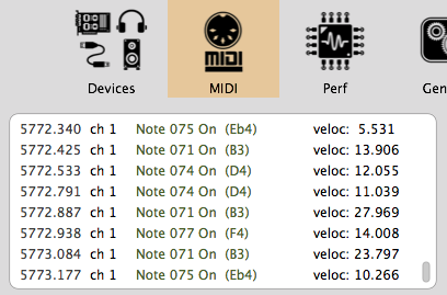
Yesterday it was possible to form the sent midi message in such a way that the software on the computer could recognize the midi as a hi-res midi. Thus potentially midi resolution can be 127*127(14bit). But so far, not everything is so smooth. With a keyboard polling time of 3.6-4 µs for my device, it turns out that midi hi-res capabilities are fully enabled at speeds up to ~11(velocity). Higher speed - resolution drops. Speed 60-61(midi-velocity) is divided into 6 steps. And at speeds of 125-126-127 - the resolution of the device is enough for the usual midi resolution.
The delay is also pleasing - the message flies to the usb channel 20-30 μs after the event.
Small video..
Very nice progress!!
Perhaps the best gift for the New Year!
Move on!
How is the progress going on? 🙂
Good time!
The boards made for testing showed that they work. They work in the sense that the circuit performs its function. Sensors work, signals come. Observation with an oscilloscope showed that some signal distortion does not seem to interfere with normal operation. But I have not yet installed the boards over the hammers in order to understand HOW these boards work qualitatively. But nevertheless, I decided to manufacture the entire set of boards for the entire instrument.
In the fall, I spent a lot of time arranging the parts on the board in such a way that the automatic routing could complete. But I still didn't like the result. All the same, several dozen connections remained under-routed. And there were many deformities in the paths of the tracks.
Then my work began. I work as an accompanist at a music school and accompany students on the piano who are learning to play the saxophone, oboe and percussion instruments. This reduces free time and energy for enthusiasm and study + the body has become more lazy after the covid period. (we are gradually coming back from this and getting stronger)
After the new year, I redid the boards and made all the connections by hand. It also took a couple of weeks. Then I expected some sub-accumulation of funds in order to place an order for the manufacture of boards. About a week ago I tried to order production and ran into some difficulties. I chose to make in Taiwan as the cheapest. In Russia, you can order production from local manufacturers, but it comes out 5-20 times more expensive + there is no convenient editor from which you can immediately start production. Production here, apparently, is focused on large batches and the production of small series of boards is extremely unprofitable (+ fuss with documents is very difficult for me).
First of all, the difficulty turned out to be that it was impossible to pay for the order from Russia and produce boards with surface mounting of electronic components. America simply forbade Taiwan from doing so.
But, nevertheless, I tried to order and the manufacturer did not yet have the required number of qre1113 sensors for production (this is still the second difficulty). While the process is waiting for the sensors to arrive at the warehouse. I expect that in a month and a half everything will happen!
If everything works more or less, then I will try to post a description of this project.
And so, attention still goes to learning C++ programming, learning how Git, Сmake, Qt, Openframeworks work, and Linux features. During this period, it was very interesting to program the barometer on the ESP32 with a small screen and output information to the home network. It was interesting to make a ws2812b LED lamp. It was interesting to start programming the synthesizer on physical simulation. It was interesting to start programming the Fourier wavelet analyzer. It was interesting to parse Pomodoro timer data and display charts on the screen of an Android phone. Well, you need to sleep well))))
It all eats up a hell of a lot of time.
So it goes...
scherbakov.al
How's the progress going? 🙂
The package with the boards was received by a friend of mine in a neighboring country. Soon she will come to me!
scherbakov.al good. We will be a
Waiting for update🙂
BTW, are you living in Russia?
Yes, I live in Russia.
scherbakov.al
If possible, please write to me on PM, I have one topic to you. Thanks 🙂
A certain stage has been passed and the keyboard starts playing. There are still problems and bugs, but overall I am happy with this device!
That's very nice!
Would you mind explaining how does it work?
Why does it have LM393 voltage comparator (another elements) per key/optical sensor, etc?
scherbakov.al congrats, that’s a great result already! How does it work, have you used an existing design or it’s your own design?
The optical sensor responds by changing the voltage to the distance to the hammer. This voltage is compared using a comparator. Data from the comparator goes into a shift register, which collects data from many sensors and transmits it sequentially to the microcontroller pin. In the microcontroller, if a signal is present, an interrupt is triggered in which data associated with the timer value and a specific sensor is processed. Next, a midi message is generated and sent to the computer.
CyberGene I would like to express my gratitude for the inspiration your project provided! A few years ago, digital pianos with real mechanics came out that I was drooling over, but the prices were completely unaffordable for me. And then you go and do something similar to Yamaha or Kawaii! And I thought, why not? And the Cybrid project showed that anything is possible!
Perhaps the circuit with comparators and optical sensors was borrowed. It is also quite common on the Internet (sites about Arduino are full of something similar). Next.. - shift registers and what follows them along the signal path had to be invented by myself. Some logic chips had to be added between the shift registers and the microcontroller to “cut” the signals. I also came up with the processing code myself. Cool C++ language. I like!
scherbakov.al I would like to express my gratitude for the inspiration your project provided!
Thank you 🙂
scherbakov.al shift registers and what follows them along the signal path had to be invented by myself.
That’s quite interesting although I’m not sure I understand it but I had to just read what shift register is, so maybe I need more time to think of it.
Do you use trimpots to set the comparator voltages?
Again, great job! And excellent playing 👏🏻