AlexanderBunt
I made a new trhead for the questions about my hybrid carillon project. Since there are that much questions that the other thread would be too full…

I made a new trhead for the questions about my hybrid carillon project. Since there are that much questions that the other thread would be too full…
I am starting to become a bit desperate, if I may call it that way… ;-)
I just can't get the wiring right for the sensor.
This is my circuit, with on top the black sensor (think that isn't the led) connected to 3.3V and a 2k resistor (for now).
The led part (at least I think this is de led part) is connected to a 220 Ohm resistor and to the ground.
But the values I am getting are just 3.3V. Nothing reacts to my movements on the sensor… Even when I deattach the sensor or replace it with another, nothing will happen.
Who can help me with this problem…
Point is that I don't understand the sensors I think… thats why I can't resolve this. Also, the scematics on the internet are all different.
AlexanderBunt a new trhead for the questions about my hybrid carillon project
Great! I was about to suggest this.
AlexanderBunt Haha well spotted… I'm Dutch😇
Nice! We're fellow countrymen, then 🙂.
Cheers and a happy project,
HZ
HZPiano So I'm not the only one on this forum who is Dutch, that's nice to hear!
Thank you very much! I aim to have this all working in the future…
Wauw, I made a very stupid mistake… inverted exidentialy power and the ground coming from the arduino😂
AlexanderBunt inverted exidentialy power and the ground coming from the arduino
It sound like the problem is solved? Here is one trick to keep in mind with these sensors: the LED light is IR which is invisible to the eye but it is visible to most cameras, including smartphone's ones. Just framing the sensors in your smartphone camera app will reveal if the LED is shining light, how bright it is compared to background illumination (even though this is much more complicated to get it right, but the camera will give you a ballpark and nudge you to make "shadow" for the experiment), and interesting, if the area is dark enough, how much IR light is reflected by your target. All very useful in my experience, rather than walking in the darkness 🤣
RIP Yes the problem is solved. Now I'm going to do some experimenting with the resistors to find a right balance between precision (higher value) and a good value to work with (lower value maybe).
And, jeah knew that…
Can someone ( @CyberGene @JayKominek @RIP ? ) maybe help me with some basic code examples for how to setup a fast scanning/reading method with multiple CNY70's on an Arduino or Teensy? Just a push in the right direction…
Just a whole lot of if else statements won't work I think (far too slow) and makes a true mess of the code of course.
AlexanderBunt Just a whole lot of if else statements won't work I think (far too slow) and makes a true mess of the code of course.
This isn't necessarily true. For instance, when you want fast digital read on the Teensy, they advise that digitalFastRead() works only with a pin parameter that is a constant, e.g: digitalReadFast(10) instead of looping some variable and doing digitalReadFast(i). That is why my code looks so ugly with no for loops. As a Java dev who is used to writing nice code that goes through merciless reviews, I couldn't look at what I had to write for the Cybrid 😃
I'm not sure that applies to the analog read though.
As to advices for writing the code, I can give you a very simple example in how to loop through multiple CNY70-s by using the Arduino based (high-level) language, however I'm afraid you may need lower-level C-stuff that would directly use the underlying microcontroller and I'm of no use here since I've never been good with low-level programming...
AlexanderBunt I don't have any useful Arduino experience. In general you'll want to arrange for something which can, on a regular schedule, just read all of the relevant ADC channels and store the values. Then once you've grabbed them, do whatever checking you want.
Controlled timing can be more important than "fast". If you just check things as fast as you can in a loop, then any conditional code execution will make some iterations of the loop take more or less time than other iterations which might cause you difficulty timing things. Depending on how you implement things.
AlexanderBunt Just a whole lot of if else statements won't work I think (far too slow) and makes a true mess of the code of course.
This is being compiled down to assembly to run on a microcontroller, if the task fundamentally requires a bunch of "if else statements" then you're going to end up with a bunch of compares and conditional jumps one way or the other.
The standards for what constitutes messy firmware differ, IMO, from the standards for high level code running on luxuriously overpowered desktop/server processors which just need to respond fast enough for a human.
JayKominek The standards for what constitutes messy firmware differ, IMO, from the standards for high level code running on luxuriously overpowered desktop/server processors which just need to respond fast enough for a human.
In the world of high-level languages like Java, what is most important is easy maintainability of the code and self-explanatory code. Even a ternary operator is undesirable when it will take 10 additional seconds for someone else to read it 😀 I'm so used to these requirements, I had real difficulties understanding low-level code examples for the Teensy and I just gave up. It's a bit of a shame when I call myself a developer but that's the reality 😳
CyberGene I can give you a very simple example in how to loop through multiple CNY70-s by using the Arduino based (high-level) language
Well, that would be nice I think. I have never done any low-level coding, so that won't be my strongest point either. But maybe the if-else structure wont be that bad then. My only concern: if you make a statement like this:
Will be key 27 much slower than key 1…?
So, CyberGene is you can cive that example? Would be nice.
CyberGene Yeah for me the same. Used to write in languages as C# and JavaScript/React, so this stuff is very new for me.
JayKominek In general you'll want to arrange for something which can, on a regular schedule, just read all of the relevant ADC channels and store the values.
Exactly, but maybe just a loop over all values will be the best (and ugly) thing to do… I don't know.
AlexanderBunt Will be key 27 much slower than key 1…?
Assuming you have a while (true) loop around each ifs, no, each key will be the same. However as Jay said there may be latency on how long it takes to do the entire loop in case what you do into the "ifs" are time consuming. If you are just setting shared variables for another thread to act on (e.g. send MIDI packets), I think this loop will be fine.
And remember: premature optimization is the root of all evil, so just try it, see what happens, gain experience and change what it doesn't perform as hope.
PS: I have not done any Arduino either.
RIP Yeah doing that now. Trying and see what will happen. Thanks for the help.
Will keep you posted.
RIP And remember: premature optimization is the root of all evil, so just try it, see what happens
Wise words, as always...
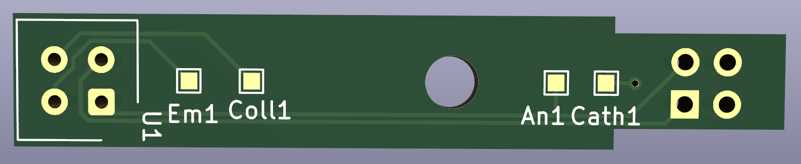
If I want to use your sensor board, where do I have to place which resistor and how does the CNY70 sensor be placed on the board?
For example this board:
I think the led resistor should be on Em1 - Coll1, and the phototransistor on An1 - Cath1. But am I right?
AlexanderBunt If I want to use your sensor board,
Have you tried to use KiCad for the purpose? All the information you are asking should be there.
Start https://docs.kicad.org/5.1/en/getting_started_in_kicad/getting_started_in_kicad.html if you don't know what I'm talking about.
PS: sorry if I sound too blunt, I'm just trying to protect Jay from too many questions (including my own 🤣)
AlexanderBunt That appears to be my 2020-offset-1x board. It doesn't have any resistors on it. The labeled pads you're seeing are test points.
The LEDs in my design are driven by a constant current source, so there aren't any resistors used to control LED current. Similarly, the phototransistor collector is attached directly to +3.3V, and the emitter feeds into a transimpedance amplifier. So there's a gain resistor for that, but it is located adjacent to the relevant op amp.
The orientation of the sensor is easy enough, though. The markings on one side of the CNY70 should be facing left in that image, away from the U1 silkscreen.
My document here https://github.com/jkominek/piano-conversion/wiki/Analog-Stage-Theory-of-Operation explains how my system powers the CNY70 LEDs, and then gets/makes use of the signal from the phototransistor.