Skip to content

DIY Digital Piano: Hickman Action

Mike Filip

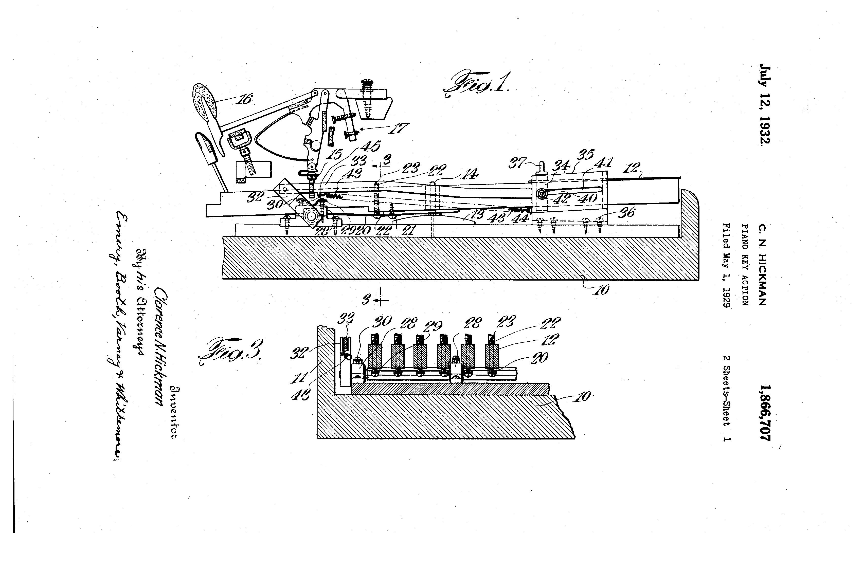
So this is an offshoot of the main thread. To summarize: I am working on a fully DIY digital piano with a custom key layout different from the traditional 7+5 of the regular piano. In the main thread and other sub-threads I will cover the Janko layout, electronics, assembly, firmware, etc. However in this thread I will talk/discuss the Hickman action specifically. Here is the video discussing this that I put together.


Now, even though I decided to go with a digital piano (as I am woefully unprepared to try to build a full acoustic piano), I did want the feel of the piano to be as close as I could get to a grand piano, meaning that the action inside the piano had to be that of a grand piano.

Unfortunately the grand piano features the Erard double escapement action which is rather complex, meaning that the best option for me would have been to buy a used action somewhere and cludge my janko piano on top of it. This would have necessitated some complex key levers as the janko layout has a 5.1 inch octave span while the grand piano action was designed with a 6.5 inch span. In the end I decided to just build a completely custom action instead, with 9mm width of the action parts instead of the 16mm parts in all traditional pianos.

Just as I was about to start designing the parts for the Erard's action I came across a video where the author was working on rebuilding an old acoustic Hickman action piano - which is what lead me down this particular rabbit hole.


The way the action works is rather simple, but I explain it better in the video along with visual guides, so I will forgo doing so again in this thread. Instead I will open it up to questions along with providing any extra details if necessary.


Mike Filip

Pin connections:

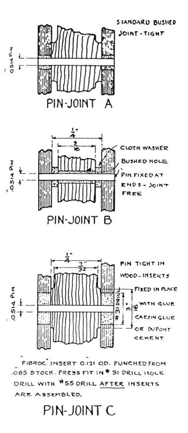
The Hickman action features 2 more joints that are different from the typical piano action (for a total of 3 types):


Pin joint A:

This is your typical bushed joint that is used in most grand pianos. You have a centerpin of around 1.2 to 1.4mm diameter going through the center, binding tight with the part going through the middle of the joint (typically made out of wood, though composite materials have started to be used more recently), and connecting to the second part via the two outer parts that have a felt bushing between the part and the center pin.

The felt bushing is glued in place and prepared so as to provide 'just the right amount' of friction.

Pin joint B:

Think of this as the inverse of pin joint A. The felt bushing goes on the inner part instead of the outer, while the centerpin is held in place by the outer part instead of the inner. The additional cloth washer is just there to prevent binding between the two parts. Overall this joint is a lot looser than joint A - since the felt bushing is by its nature soft, meaning it can squish a tiny bit. This is undesired in joint A which needs to prevent as much side-to-side motion as possible, thus has the felt on the outsides, but for joint B this is actually desirable behavior, so the felt is placed on the inside to allow for more side-to-side motion.

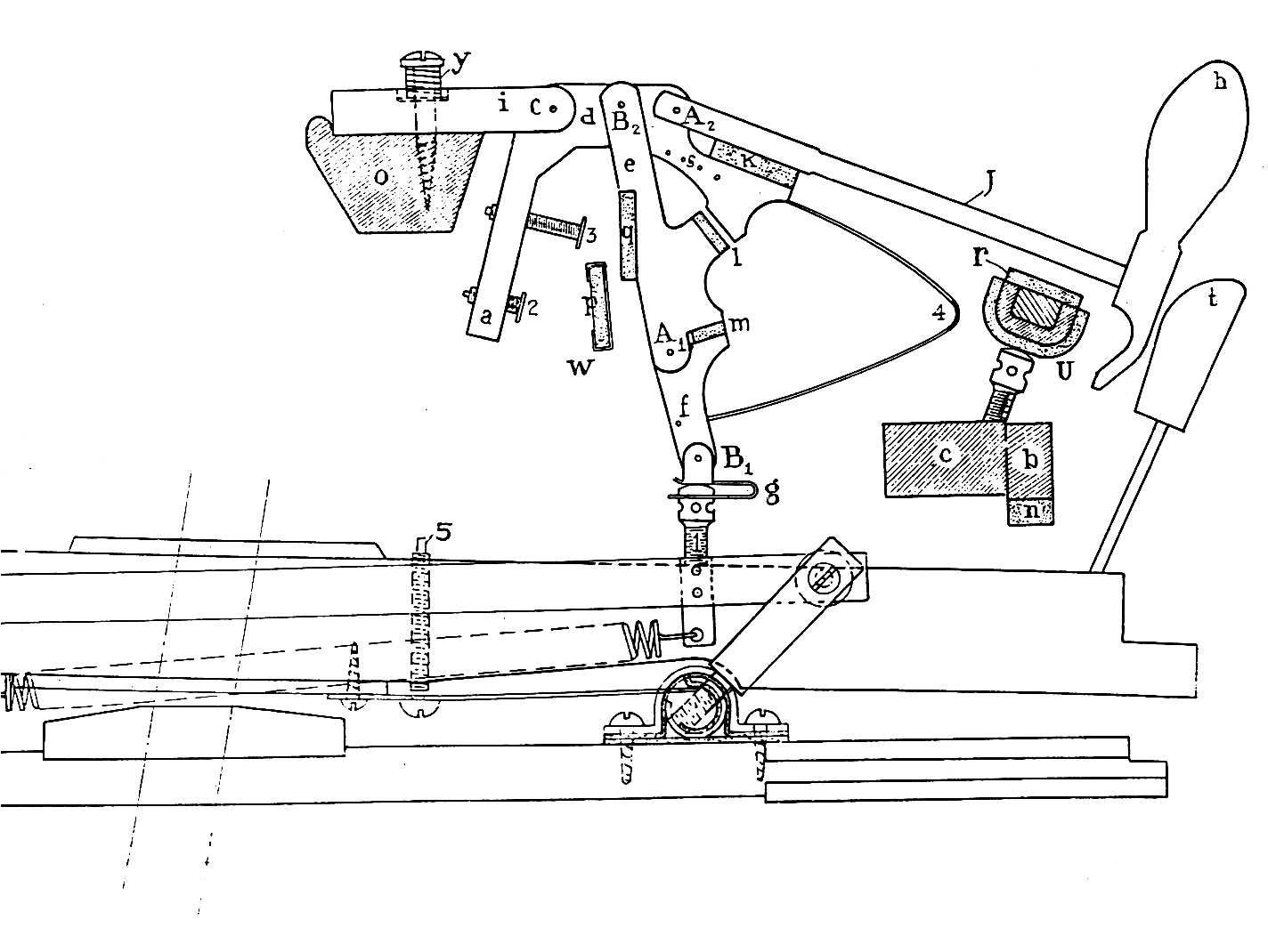
In the Hickman action this joint is used in places such as B1 and B2 where tightly connected joints might cause binding - the key for example isnt going to move side to side, and neither should the flange (i) & driving lever (d). So the jack (e & f) needs to have some side-to-side movement without binding the action.

Pin joint C:

This is basically the same as pin joint A, just using a hard bushing instead of a felt one. There have been attempts at using something similar in regular piano actions with PTFE bushings, but it failed over time when the wood expanded due to the effects of humidity leading to the action binding when the hard bushing pressed at the center pin.

In the case of the hickman action they tried using a larger bushing insert and changing the material, though how well it would have worked out isnt known due to the failure of the hickman action at carving out a space for itself in the piano market.


Personally I use both A&B joints throughout my design (complete with felt bushings), and have recently shifted a few of the joints to type C as well (with PTFE bushings) due to them working out rather well for the 1.5mm pins that I need in the key-lever part of the action (which is not part of the hickman action, so…)


Mike Filip

Weight adjustment device:

The Hickman action also featured a way of adjusting the key weights of the entire piano simultaneously via a single lever - basically allowing the player to 'dial in' their preferred key weight from ~40g to 80g (or so - the actual values arent stated).


Essentially there was a lever at the left side of the piano that could be shifted to rotate a central rod running beneath the keys that would tighten or loosen a leaf spring between each key and said central rod. Each key's spring could also be individually calibrated to dial-in the weight of the given key, theoretically making weight adjustment easier as you no longer had to plan out key weights, drill out the holes for them, and glue them in - you just adjusted a screw.


One thing to note here is that this makes the action be a kind of hybrid between weighted action and synth action - as in addition to the hammer & key weights (which add an inertial feel to the entire thing) there is also a spring (which doesnt carry an inertial feel) similar to a synth action.

In my design I at first ignored this system as I was planning to just dial everything via weights to 50g, but after the first prototype I had to add this system as apparently the spring here actually helps out with ensuring the repetition of the action works correctly - so even though the weight adjustment isnt really 'part' of the Hickman action it is actually rather important and does have to be included.


RIP

Mike Filip Instead I will open it up to questions along with providing any extra details if necessary.

Fantastic explanation! I resisted my typical dislike for videos (and YT videos in particular) and watched yours. It started a bit boring (for me) with all the introduction about other actions which I know fairly well, but I really liked your explanation of the Hickman!
First question: in the quest of simplifying your work have you considered making the hammer (A2) just one piece with the driving lever (d)? Doing so removes one regulation point (the stop rail) so it calls for more accurate built, and removes the corresponding flexibility wrt let-off, hammer hitting the strings, repetition engaging and so on. On an acoustic that flexibility is essential to achieve the "perfect" way to hit the strings, but with a digital maybe that's not needed? Of course I have not tried this, so maybe I'm missing something and it won't work, and if so I'm curious to know what. Because while this is definitely a great simplification compared to the double escapement action, it's still quite a lot of parts to assemble and removing one centerpin to drill, ream and bush is not negligible in the assembly. And of course one less thing to regulate.

On a similar vein, have you consider replacing the hinge in B1 with that complicated attachment with a custom capstan with a traditional heel (such as these which of course you can 3D print to spec) and traditional capstan? Or would that have made the "automatic break-and-reassemble" of the jack not work? I mean, I can think of some ideas to prevent that sort of problem, but I'm sure you must have thought that hard already, hence asking!

Mike Filip and have recently shifted a few of the joints to type C as well (with PTFE bushings) due to them working out rather well for the 1.5mm pins

Oh, great to hear that after our other conversation on this topic. Nice that they're working well for you!


Mike Filip

RIP First question: in the quest of simplifying your work have you considered making the hammer (A2) just one piece with the driving lever (d)? Doing so removes one regulation point (the stop rail)

There are several issues with this:

  1. In my particular case (and with a full acoustic action) the hammer needs to be disconnected from the driving lever in order to be free to fly up. In my case this zone above the maximum limit of the driving lever is where I position the velocity sensors, so if the hammer lever was welded to the driving lever there would be problems with recording key-hits. I could bypass this issue by using the magnetic sensors for the key-hit recordings (essentially removing the optical velocity sensors at the hammers), and is something I am thinking of doing for the 'simplified' action - though at that point it makes more sense to not just simplify the hammers but the entire action (aka: replacing the hickman action with just a single 'weighted hammer').
  2. In the hickman action description there is actually a mention of having the two parts be joined more solidly, basically relying on the natural flex of the hammer shanks & flange to allow the hammer to hit the string. I am not sure if it would work all that well, but keep in mind that I do bush that attachment extremely tightly - to the point that a 'hammer drop test' will not just not swing, but will stop at ~20 degree angle without making even a single swing.
  3. The way I print out the driving lever (flat on the build plate), it actually wouldnt make too much of a difference if I was to combine it with the hammer lever or not - in either case I would need to print them separately and then combine. Yes, there is a difference between doing a proper bushing connection rather than just super gluing the parts, but still.

RIP On a similar vein, have you consider replacing the hinge in B1 with that complicated attachment with a custom capstan with a traditional heel

In this case its unfortunately not possible. You can see from the original hickman action that the joint is fully connected (with a 'clip on' attachment to a custom capstan screw) and thats because the action relies on this solid connection to allow the jack parts to lock and unlock properly. The only alternative would be to attach the bottom of the jack to another lever connected to the frame (and thus free the connection to the key to be a traditional heel), but that just overly complex for little gain.

Think about it this way - in the Erard's piano design the heel can be left 'floating' from the capstan since its attached to the whippen assembly directly - so the heel only has a single path it can take - rotating around the centerpin of whippen->frame. In the case of the Hickman action the 'heel' (g) is connected to the lower jack, which is further connected to the upper jack, which is connected to the driving lever, which is connected to the flange. This 4-link design essentially means that the heel is free to move however it feels both up/down as well as left/right, so some sort of lock is required; be it by attaching it firmly to the capstan screw or adding another link/lever that would connect it directly to the frame (in some way).


In the end the key-lever assembly is probably ~60% of the complexity (with the hickman action being 40%), so if I was to try and simplify the design in order to make it be easier to assemble (and obviously cheaper as well) I would likely:

  1. Replace the key-lever assembly with a simple parallelogram design (likely with the 'bendable links' made from PETG)
  2. Remove the 2x optical sensors for the velocity measurement and just rely on magnetic sensors for both key-on and key-off measurement. I already plan on having an 'alternate' input for key-on so as to be able to select between optical sensors and magnetic sensors in firmware, so for a 'cheaper' option just removing the optical sensors altogether (and thus allowing a simpler action) just makes sense.
  3. Replace the hickman action with just a simple 'weighted hammer' action.
  4. Remove the inbuilt PC, DAC, touchscreen, etc…. basically convert the design to a pure MIDI keyboard that relies on an external device for producing sound.

RIP Oh, great to hear that after our other conversation on this topic. Nice that they're working well for you!

Yep, thanks for that! the back rotor that hold the backcheck was always a bit too 'loose' in terms of side-to-side sway… not enough for me to really worry about it, but still an annoyance as I had no option but to use the 'felt bushing in the middle' (type B) joint. When you mentioned the PTFE tubing I found some 1.5mm ID, 3mm OD that fit just beautifully. 30 min later I replaced the 3 1.5mm joints I had on a single key with PTFE tubing and it worked out great. Cant feel a difference between the felt bushed and PTFE bushings, but the parts are more rigid in terms of side-to-side sway.

Really too bad I cant find any 1.3mm PTFE tubing. You posted the link to one, but that doesnt seem to work for me and I cant find a working alternative on amazon / aliexpress. Seems like the sizing goes 1mm, maaaaybe 1.2mm, 1.5mm, 2mm, etc. Would have preferred to switch the other 3 pins of the key-lever assembly to PTFE bushings as well (at least to see how it worked out), but unless I find 1.5mm piano center pins or 1.3mm PTFE tubing that seems like a 'wish it was so' option.

Now if only I had access to a markforged printer… I tested one previously (work related), and its ability to print out parts with inlaid carbon fiber (as in - a second extruder that lays down a string of carbon fiber after the plastic to work much the same way as iron bars do in reinforced concrete)… The parts are basically at the aluminum level in terms of strength, so if I made (for example) the flange, driving lever, and hammer parts out of it I would likely have a much more structurally sound design with much less side-to-side sway than I do right now.

vagfilm

Mike Filip please, spend some time explaining your thoughts on the springs…


Mike Filip

vagfilm please, spend some time explaining your thoughts on the springs…

which ones in particular? The design features 3 sprints (per key), with 2 of them being part of the hickman action and the 3rd being part of the weight adjustment mechanism.


In terms of usage;

The repetition spring is there to reset the jack (as without it not just quick repetitions, but the entire mechanism will not function), while the driving lever spring is something I had to add to the hickman design in order to get the repetition working properly at speeds higher than 10/s. In the original hickman design that spring isnt there and I believe the 'issue' was solved via backcheck adjustment (plus the way the backcheck operates when attached to a full key lever as opposed to my rotor design).

The weight adjustment mechanism is pretty much the same as the springs on synth action keyboards - it pushes down on the back rotor which in turn pushes up at the key, effectively taking care of ~20 (to 100) grams of key weight. This does mean that at the heavier key weights (100g) the keys start to feel 'springy' (though there is still a hammer / inertia feel to them even then), but at the 'normal' range of 40-60 grams it feels more like a very responsive hammer weighted keyboard instead (as it was designed to be).


As for spring material, I am not sure what actual piano springs are made out of (plus they cost quite a bit to order and arent of the correct size to boot), so I ended up using piano wire.

Not sure if its actual 'piano wire' or thats what they are called, but they were recommended as good options for custom springs, for which they worked out great.

Originally I got a few 'samples' from howard's piano shop, but once I selected the correct diameters (and discovered that pre-bent springs are more difficult to work with), I bought a few straight sections of 500mm length. Cutting was at first done with a dremel tool (lots of sparks), but later with a specific spring cutter.

Size wise I went with 0.032 inch wire for the repetition springs, 0.039 inch wire for the weight adjustment springs, and 0.047 inch wire for the driving lever springs.


Wherever possible (and where the springs might 'rub' against parts) I glued in some guidepin bushing felt (as I think thats the closest felt used for 'metal rubbing against felt' scenario) just in case the springs would start to carve into the plastic (most important in the back rotor section as every key press requires the spring to move ~1mm in/out, rubbing against the rotor (or its felt).


vagfilm

Thanks for the detailed reply. I was curious about the spring above the hammer since that spring is not part of the Hickman design (or regular grand action). And when you mentioned that repetition improved when you added a spring, I thought you were refering to the weight adjustment spring and not to the driving lever spring.


Mike Filip

vagfilm

The spring was necessary to prevent the hammer backcheck from being hit by the hammer too early thus causing the backcheck to not check the hammer at heavy hits - especially for the lighter hammers.

Here is a slow motion shot of the operation without the spring - you can see how the driving lever rotates clockwise after the hammer hits the hammer-hit-felt, forcing the bottom of the hammer to extend and hit the backcheck, sort of bouncing off it instead of getting caught when the driving lever rotates back counter-clockwise (leading to this sort of 'snapping' motion).


RIP

vagfilm I was curious about the spring above the hammer since that spring is not part of the Hickman design (or regular grand action).

Excellent question, thanks for asking it @vagfilm

Mike Filip The spring was necessary to prevent the hammer backcheck from being hit by the hammer too early thus causing the backcheck to not check the hammer at heavy hits - especially for the lighter hammers.

Great answer, thanks for taking the time Mike. This Hickman action (and your small mods to it) is definitely more sophisticated that I thought at first, and I come to appreciate it more. Too bad that it did not caught up for acoustic pianos for the reasons you mentioned in an earlier post.

@dore_m WRT my possible use of this design for my next DIY thing (and I have not completed yet the current one….) with a smaller octave span, I am still on the fence. I like it, but I still think it's too much work for me to print, drill, bush, ream that many holes for that many keys, so I'll experiment more with other simplifications.

All: I moved these few messages from the other conversation to this one, to keep things neatly organized for future site visitors and our own future selves.


heathen

@Mike Filip

Привет, Михаил! Thanks a lot for such a detailed description and awesome implementation of your project. I'm a bit of perfectionist by myself, and this is the level of details. Снимаю шляпу!

The Hickman action is something which really got me. I'm thinking about DIY a digital "grand piano" and initially thought to find a donor on sale to salvage a full "keybed + keys + actions" module and just add electronics and casing. But traditional double escapement action is complex and hard to maintain, and this fact was worrying me. When I saw your project and all the details about the Hickman action, I was impressed by how much less complex it is in comparison. Don't know how real all the promises in Hickman's description (I've spent some time reading the sources you provided) but it sounds remarkably interesting.

And I've got a practical question: what do you think about longevity of the 3D-printed action? How long would it survive in case of actual wooden keys and expressive playing? I mean, the whole part above the key?

And thank you again for the inspiration!


heathen

Btw, I just found a video with demonstraion of the action:


CrisOliveira

Do you plan on making the models in your project available for download? I'd love to print that action.