Skip to content

Build your own DIY hybrid piano - step six putting it all together

RIP

If you haven't already, look at the previous steps (perhaps skipping the fifth which is for a different option which I have now abandoned), starting from step one

The electronics have arrived and I've started putting them together, documenting the process here. For more technical documentation, see instead

https://github.com/stem-piano/stem-piano-g-main

and for video documentation check @gzpiano YouTube channel linked from github.

These are all pre-manufactured and pre-soldered boards which @vagfilm @Akari @gzpiano and I purchased together as documented here

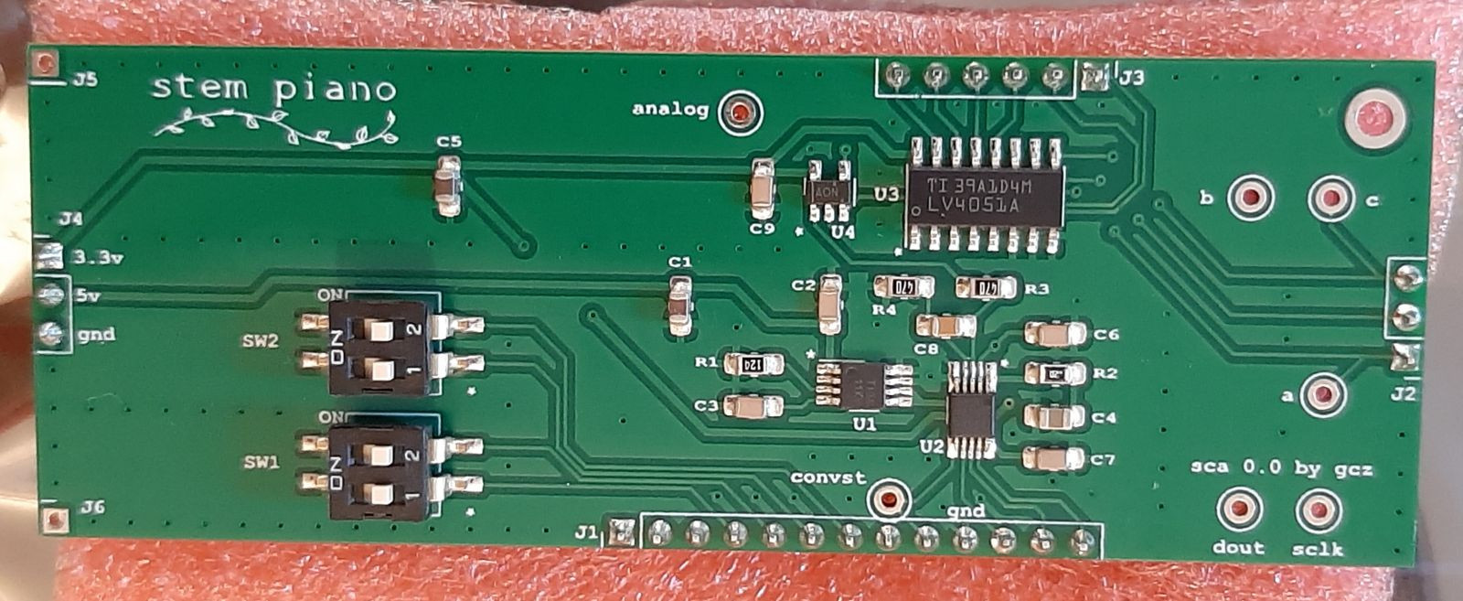
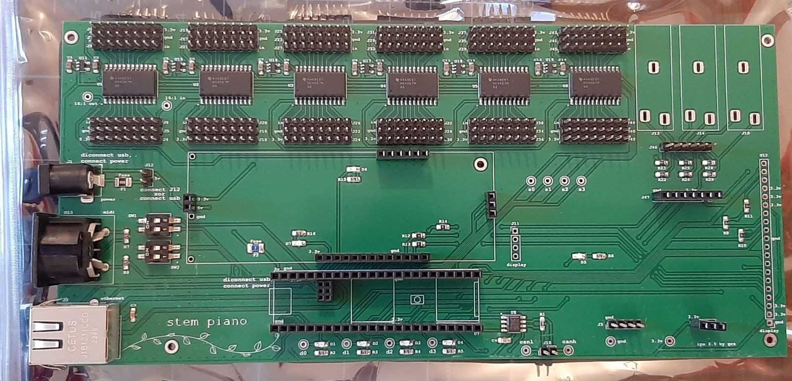
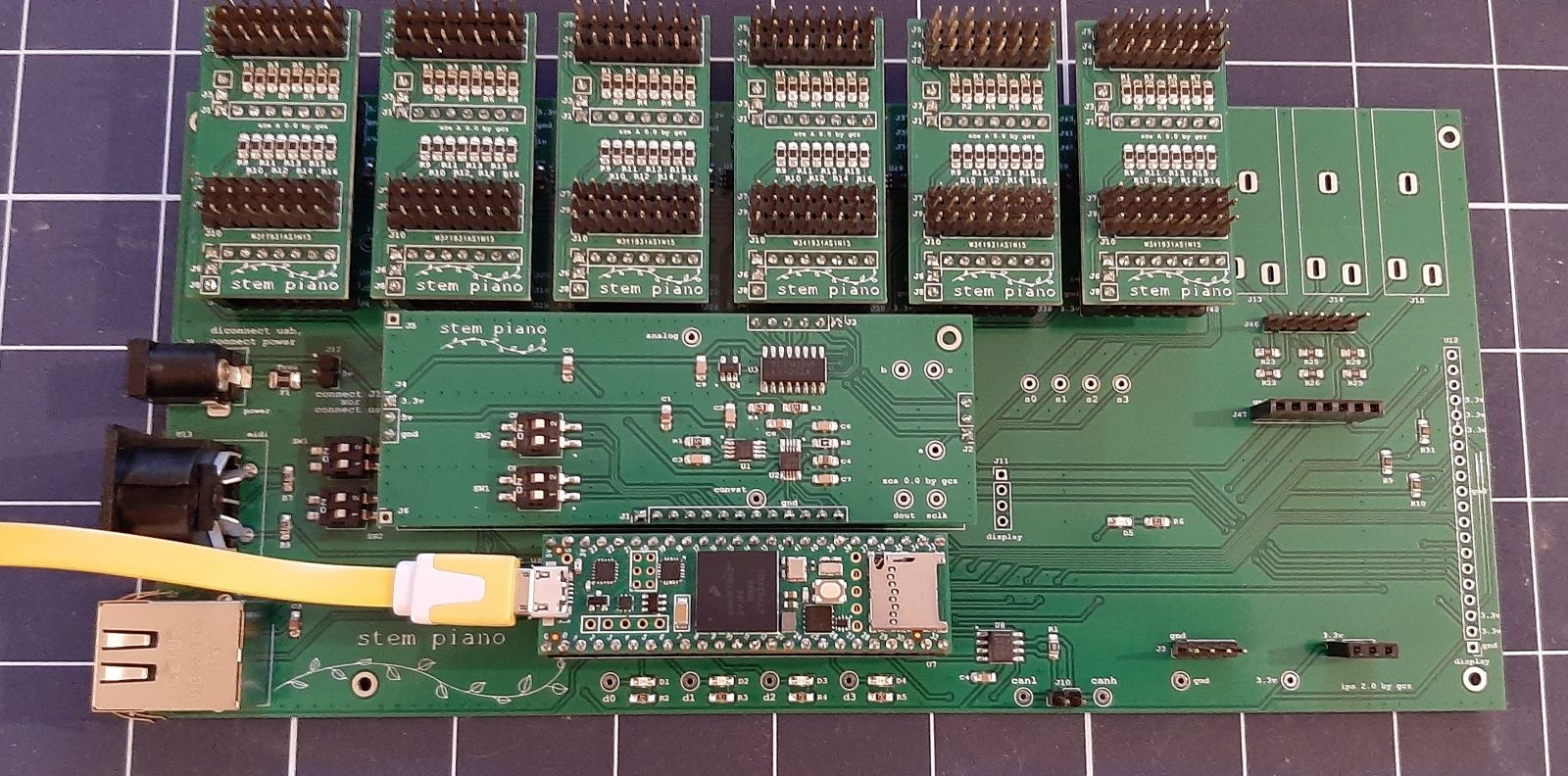
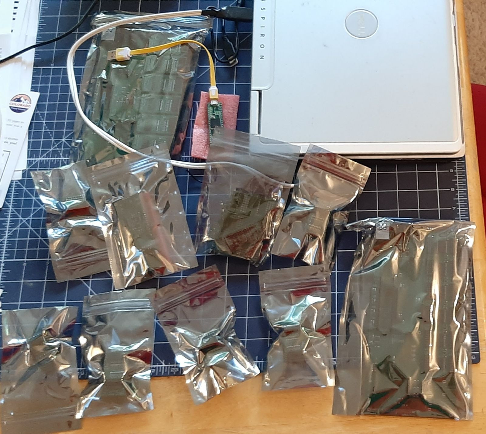
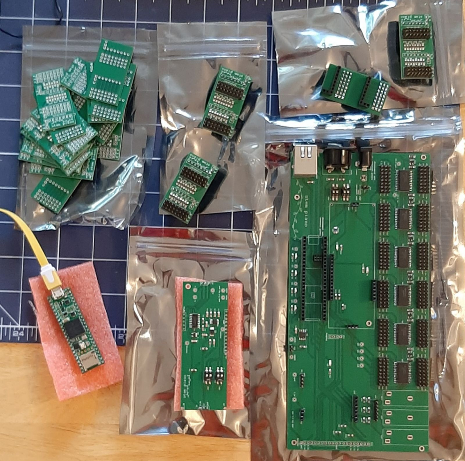
Here are the first pictures

More to follow, not sure when (I'm missing a few parts and I've placed the order, otherwise it could have been possible to have the whole instrument ready by the end of the weekend!)


CrisOliveira

Are those parts all you need to turn the action into a controller or are there previous stuff you're keeping from prior steps?


RIP

CrisOliveira Are those parts all you need to turn the action into a controller or are there previous stuff you're keeping from prior steps?

Electronics-wise that's all you need, besides that in what you see:

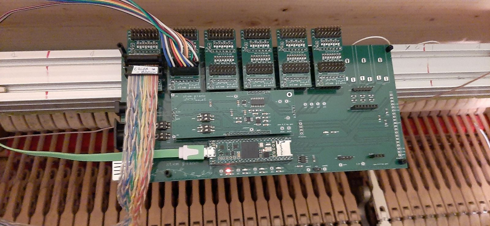
  • there are only 3 sensorboards with 4 sensors each, so this is an octave only (a spare octave): I have all the other sensorboards already installed in the piano of which you can see pictures in the previous steps
  • there will be a lot of cabling connecting the sensors to all those empty pins that you see in foreground on the left, in fact you will see that the major issues I'm nudging Greg to change are all related to making that part more convenient because it's a lot of work. Note that the sensorboards I am using are mine and not Greg's or Jay's and I am convinced than mine are a superior choice to both (happy to elaborate more if you care)
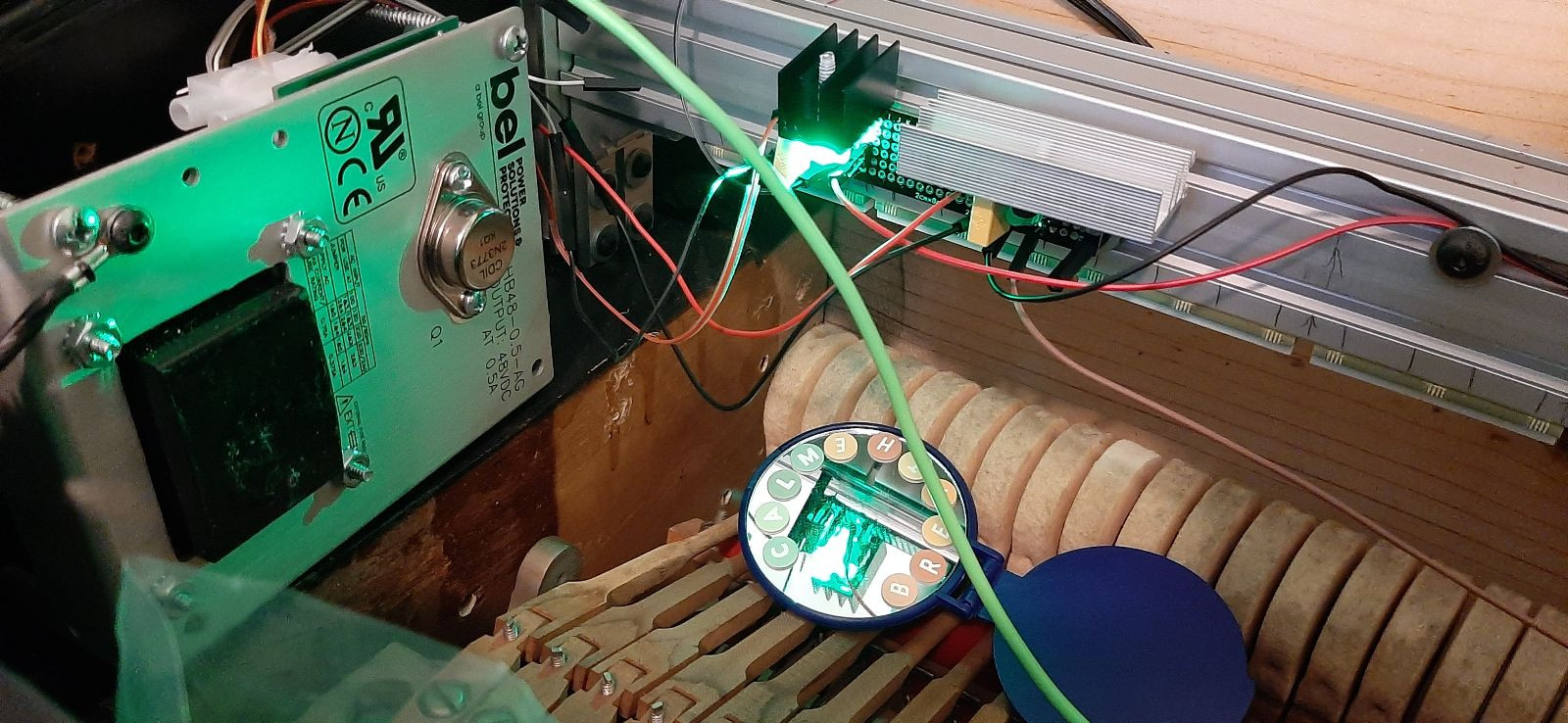
  • You don't see the power supply for the LED because I am using a makeshift one which is out of the frame (I've ordered the final one yesterday -- it's an off-the shelf linear voltage regulator which becomes a constant current with just 3 devices which look like transistors in a TO-220 package -- I'll make a post about that when ready, hopefully next weekend).
  • All the previous steps are basically discussion of options or mechanics

Hope you'll join the DIYers club 🙂


RIP

Errata:

there are only 3 sensorboards with 4 sensors each, so this is an octave only (a spare octave)

Corrige:

you see only one sensorboard with 4 sensors each, of which only one is connected to the actual controller board

Justification:

I was so excited that took the video as soon as I got it working. I later connected the full octave and tried that, but that is not shown on the video. I'm not going to remake that, just imagine three sensorboards on the left and 12 times more cabling connecting them to the control board on the right (and that is still just 1/8 of what is needed for the full piano)


CrisOliveira

Do you people plan on selling kits in the future? I already have had my share of burnt fingers fixing the display of my Juno-G. Buying a kit with all the boards with pre-soldered components would be awesome.


RIP

CrisOliveira Do you people plan on selling kits in the future?

Not exactly, but close! Greg finds soldering fun, but I don't (note*), so I nudged him to contribute to ordering everything pre-made from a vendor: PCB manufacturing and parts soldered. He kindly joined and this is what you are looking at.

He's more a YT guy than a forum guy so he posted his report there

https://www.youtube.com/watch?v=tyN7v7L9VIQ

He has soldered additional stuff because he wanted to, but everything he added is optional (and for a additional cost can be asked to the vendor to do for you)

See github for this order (which did not include the sensorboards) and see https://pianoclack.com/forum/d/681-diy-piano/15 (and links within) for the sensorboards and 3D-printed protectors order. I can make the PCBway link for this order (as I did for the sensorboards) if desired.

There are a few things to fix in both (the former may have some headers in the wrong side of the board for the ACE and the latter is single-side which works fine for hammer sensors but might be tricky to deal with with key/damper sensors). And of course assembly will be needed, but mostly cabling (see my comments above about that) and mechanics/action/cabinetry etc

For a cost perspective, the minimum order these manufacturing houses have tend to be 5 boards of each kind. The current design has the most expensive PCB board at a count of one per piano (or two if you want damper sensors). So four of us shared this order. However I'm nudging Greg to split that single expensive board in multiple cheaper boards, so that a single piano purchase becomes more cost effective, avoiding the need for this coordination. See the github discussion on this topic and feel free to join there.

We are all happy to help you making your order in the way that suits you, so just ping us on this forum when you are ready.

note* I soldered many electronics since I was young and never burnt any body parts or object, but for me soldering is tedious, time consuming (and I have limited spare time), error prone, and the fumes are not good for one's health

RIP

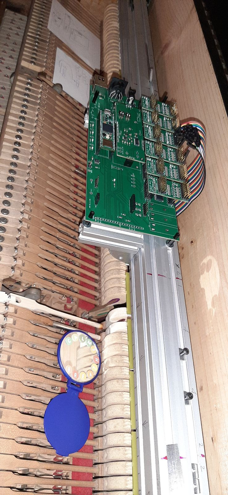
The main board installed in the instrument.

Tomorrow I should be done with the power supply too, which I made by using an off-the-shelf Bel Power Solutions HB48-0.5-AG feeding six 20mA, Temperature-Compensated, Constant-Current, CL220. I need six since each LED could drop voltage by up to 1.6V and there are almost 180 of them, so using a single CL220 would require 180*1.6V which is too much to deal with, whereas making 6 circuits in parallel would work with the 48V out of the Bel Power.

I will then be left only with cabling each sensor to the control board. For sure I won't be done with it tomorrow, however I hope to settle on one of 4 possible options as "reasonable enough to be doable". I'll keep you posted!


HZPiano

RIP

Looks the part!

Cheers,

HZ


RIP

Look! Ma! No current-limiting resistors, yet constant current! Better yet, ripple at less than 0.005%

I've performed various experiments with cabling, and not found the most appropriate, yet.

Exhibit A:

--

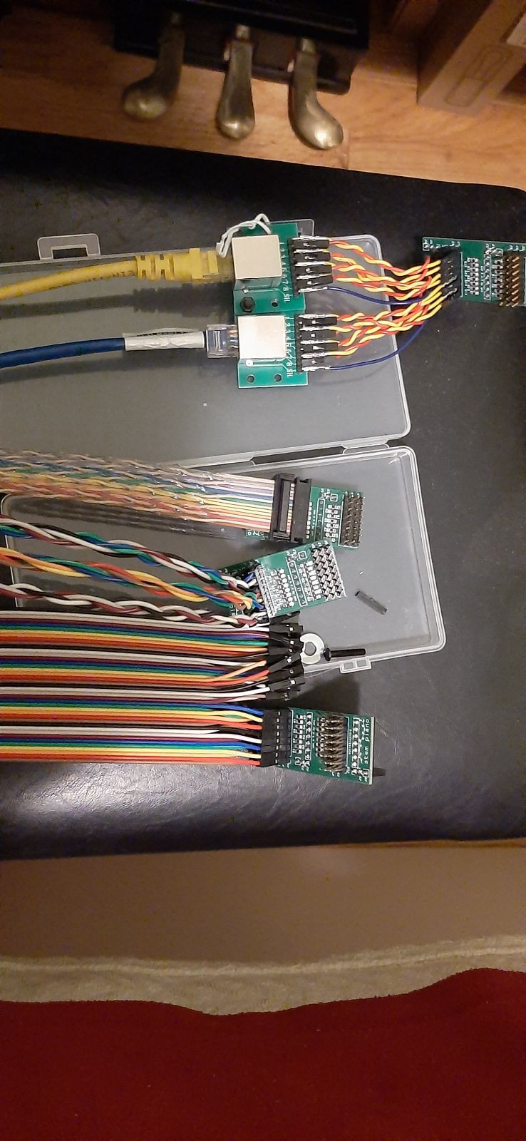
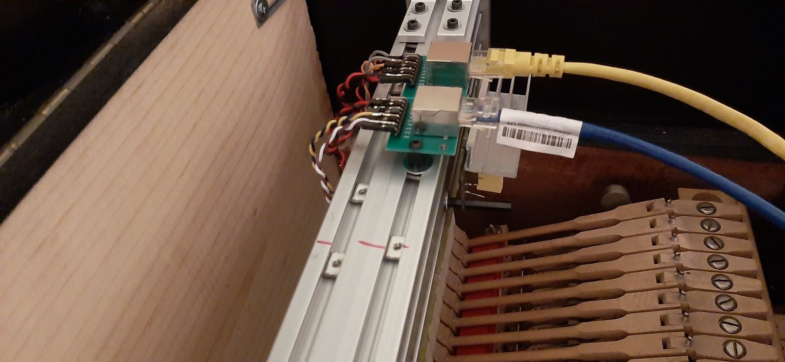
Exhibit B:

If I were designing this now, I would use ethernet connectors (the ones on top in the Exhibit B picture), and I badly kick myself for not having thought about that earlier. The semi-good news is that I could have the ACE's re-made with those connectors (the ACE's are the not expensive interposer boards in between the main board and the cables, which you can see attached to the cables on the Exhibit B picture and attached to the main board in the Exhibit A picture). Yet, I would still need to do jumper cable wiring for the sensors, unless I remake the sensorboards too, which I deem too expensive (and has other logistical/topological problems which I will spare you about).

At this moment I am leaning towards this ethernet option, but I need to do more experimenting first. In particular, the current shank-based defaults in the firmware make the out-of-the-box sound very quiet, and often missing a note-on (the note-off are always present, instead)

I need to do some calibration and a packet capture before I can settle on what cabling is most convenient yet provides best/decent/acceptable data.

Stay tuned!

@gzpiano @vagfilm


CyberGene

RIP Tomorrow I should be done with the power supply too, which I made by using an off-the-shelf Bel Power Solutions HB48-0.5-AGbelfuse.comhttps://www.belfuse.com/resources/datasheets/powersolutions/ds-bps-linear-series.pdfNo preview could be generated for this link feeding six 20mA, Temperature-Compensated, Constant-Current, CL220ww1.microchip.comhttps://ww1.microchip.com/downloads/en/DeviceDoc/20005413A.pdfNo preview could be generated for this link. I need six since each LED could drop voltage by up to 1.6V and there are almost 180 of them, so using a single CL220 would require 180*1.6V which is too much to deal with, whereas making 6 circuits in parallel would work with the 48V out of the Bel Power.

That’s a clever solution. Sad that I missed it when designing the Cybrid, would have been very useful.


gzpiano

nice progress!


gzpiano

The code includes two hammer velocity algorithms.

See the hammer_settings.cpp file and the hammer_strike_algorithm variable.

The default is 0 which doesn't require precise thresholds but does make assumptions about tracking the hammer motion starting from its rest position.

The other option (1) uses a threshold at the letoff. Looking at your setup, you may want to use hammer_strike_algorithm = 1. Then, adjust the strike_threshold value, and possible the velocity_scale value.

I made a video showing the hammer position for all 88 keys when playing the piano.

https://www.youtube.com/watch?v=AWMlzoCq9G0


RIP

gzpiano I made a video showing the hammer position

I saw that, thanks!

gzpiano The default is 0 which doesn't require precise thresholds but does make assumptions about tracking the hammer motion starting from its rest position.

The other option (1) uses a threshold at the letoff. Looking at your setup, you may want to use hammer_strike_algorithm = 1. Then, adjust the strike_threshold value, and possible the velocity_scale value.

Thanks for explaining that. I thought it was the case and I intended to explore it today, which I will now do knowing it, rather than randomly!


RIP

Further updates (I should probably re-write the same thing here and perhaps I will after I try with batteries as described there)


RIP

Before the update about this weekend, summary of last weekend work:

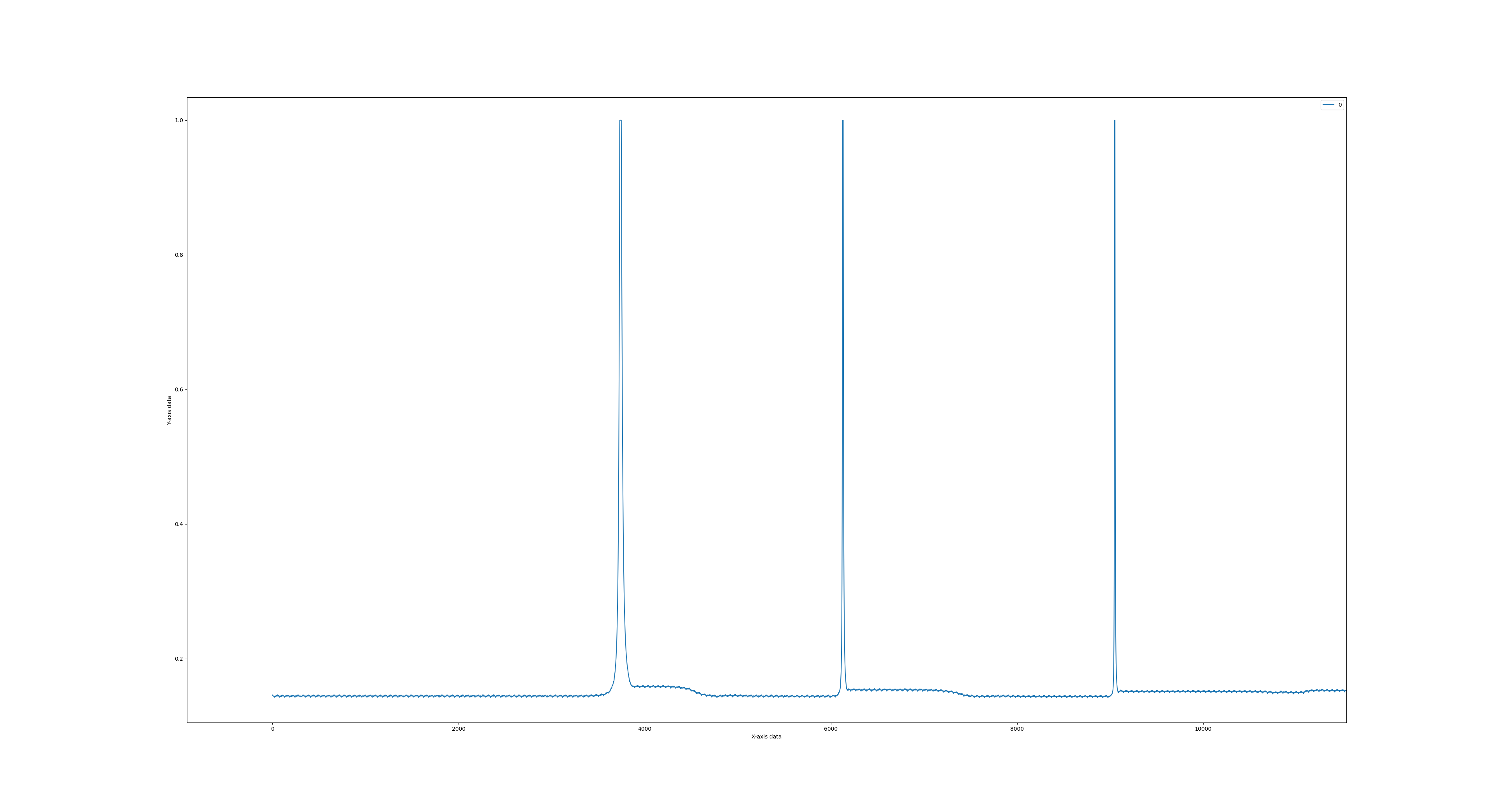
Initially I had troubles to get any decent detection of hammer movement. After playing with various parameters, with the help of @gzpiano I settled on the following, which allowed to detect hammer movements (both as ADC values and as MIDI note on and off -- even if the latter only marginally)

  velocity_scale = 0.10;
  calibration_threshold = 0.8;
  damper_threshold = 0.22;
  damper_velocity_scaling = 0.025;
  hammer_strike_algorithm = 1;
  strike_threshold = 0.7;
  release_threshold = 0.90;

The most important ones were

velocity_scale = 0.10;
strike_threshold = 0.7;

RIP

At that point, I could detect the hammer movements, which in the ADC showed as following

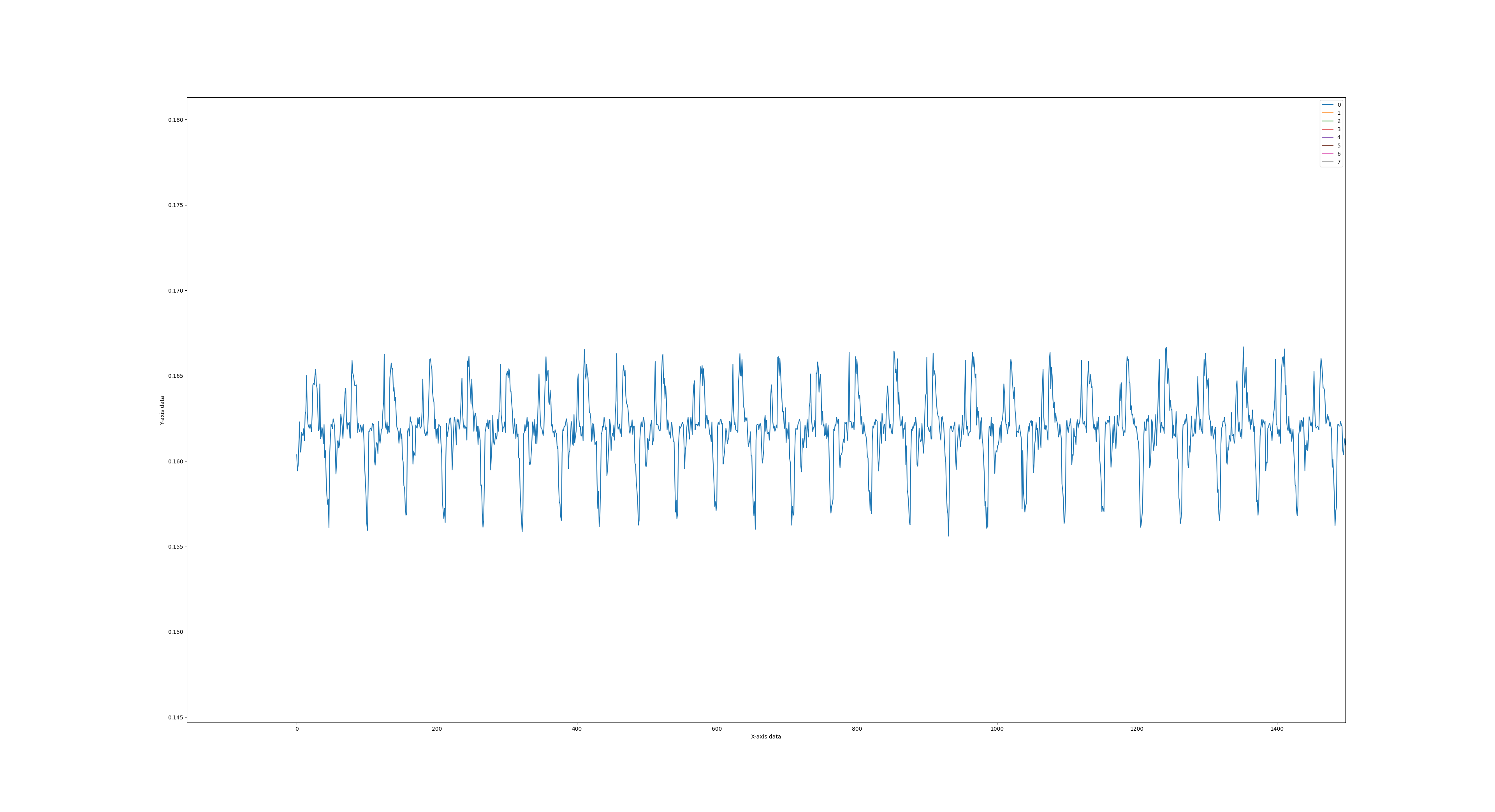
zooming closely on the "flat" areas I noticed a peculiar noise

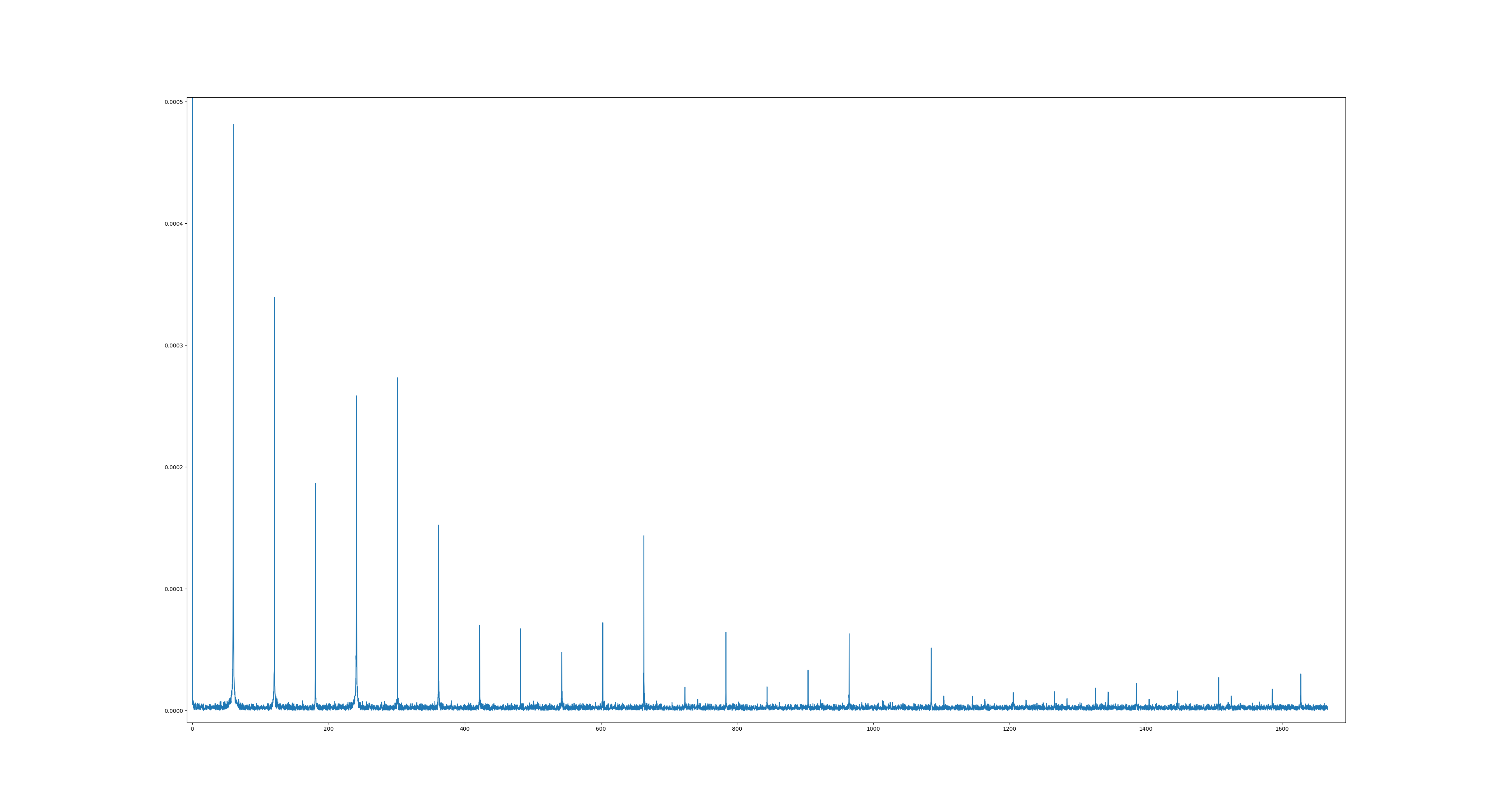
which has an evident periodicity, so moving into the frequency domain

it's clear that the noise is coming from the AC at 60Hz. Somewhat strangely, it includes very strong components from very high harmonics.

Preliminary work during that weekend did not point to a specific culprit or mitigation: light source was immediately ruled out (the piano is in an enclosure, certainly not sealed but not directly exposed to light, which I had turned off anyway and kept the door closed); any other power supply that had on hand still showed the same problems. But I did not really have good, certain alternatives (for example, I had a power bank, which most likely has a step-up from the 3.7V of the battery to the 5V of its output).


RIP

Finally, this week, I was able to fully power the system on battery (D-cells, 9V and others). All the external power supplies were off, and the only connection to the computer was the Ethernet cable.

Surprisingly, the results were almost identical!

So I concluded that one (or more) of the following must be true:

  • the noise is injected from the computer via the Ethernet connection
  • the noise is picked up by something -- the only possible external source is the computer, and the high harmonic count is consistent with this
  • the noise is generated internally by either the IPS or the SCA or the Teensy

To debug the first option, I'd have to change the firmware to save the hammer data on the onboard memory and download it later.

The second option would be very strange: for this test I am using twisted pairs (ethernet cables) connected to the sensors via very short (1") jumper cables, also twisted. And Greg is using flat ribbons, so he would be much more sensitive… even though his environment may be cleaner

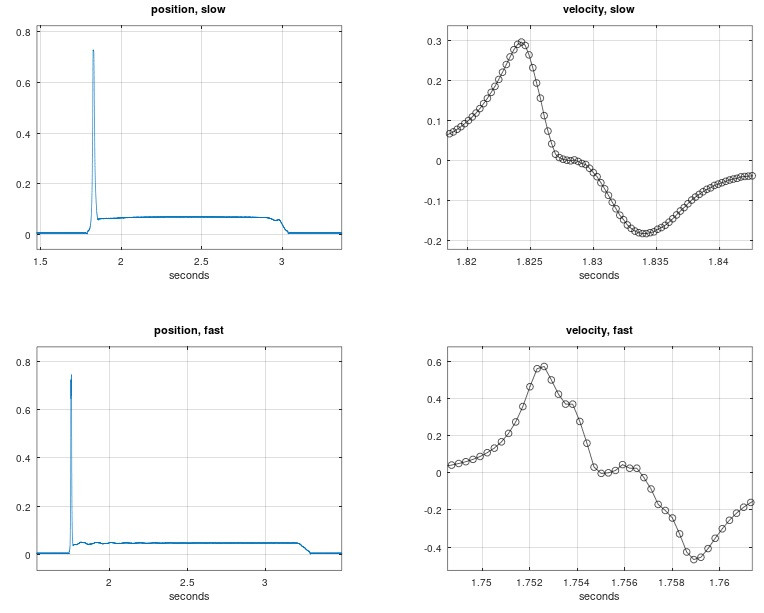
The third option would also be strange, since Greg's data does not appear to have this problem:

But this is low resolution image and not zoomed in. @gzpiano as a first sanity check before I embark in much more complicated debugging, can you please zoom in around the "zero" line on either plot on the left to see if it shows anything? TIA (and let me know if you prefer to have this conversation on github instead)


gzpiano

That's quite a mystery.

RIP can you please zoom in around the "zero" line on either plot on the left to see if it shows anything?

Just checked. It has a small signal at 120 Hz but nothing else. 1.5e-3 peak-to-peak on a normalized basis (1 = ADC full scale). I may have had lights on during the test. I've noticed that this system will pick up even faint light from an adjacent room.

With some work you could write firmware that saves a buffer of data without Ethernet connected. Then, connect Ethernet to retrieve.

Or, maybe a faraday cage 🙂


Next Page »