Skip to content

Cybrid alternative

SimonD

Hello CyberGene,

hope you are doing well,

Do you have one big power supply to feed all 18 Note PCBs at ones or you turn power on and off for each Note PCB sequentially?

(if i understand it correctly, for example, to power up 66 LM339 comparators at ones it would require 5V, 6A-8A capable power supply, not counting power for 88 CNY70 sensors)

Thank You !


CyberGene

SimonD all the modules are powered all the time, they are daisy-chained to the same power line and I use an old iPad charger. I think it’s just enough. I’m not sure it’s a good solution though. @RIP uses a better a solution as far as I remember.


RIP

CyberGene @Del Vento uses a better a solution as far as I remember.

Sorry for the late reply, been busy recently and on top of that I made a flash-trip for the total solar eclipse last weekend.

My main contribution is trying to push people to improve 🤣 and picking the best I can find around and making small things. On that regard, I believe I am the only one using the small sensors, which in my opinion are much better for aligning correctly than the larger ones. Then documenting and reporting, especially on the aspects a bit neglected by others (woodworking, mechanics, etc).
For the rest, I am pushing and waiting for @gzpiano and @JayKominek to complete their electronic design and looking forward to use one of theirs, hopefully "out of the box" or with minimal changes.

See the whole series of posts starting at https://pianoclack.com/forum/d/163-build-your-own-hybrid-piano-step-one-choosing-the-action for details (the tl;dr; version is: check the first and last message in each post)


gzpiano

@RIP - glad to have you back! Your post series is great.

I think your sensors will work with stem piano mainboard by adding a simple 88-resistor PCB in between?

For the rest, I am pushing and waiting for @stem_piano and @JayKominek to complete their electronic design

The piano I put on GitHub last November is done.

Although. this is a hobby so is it ever "done"? Present work is firmware calibration, to delete cal trimmers on sensors. Optional stuff.

Then… lots more ideas…


RIP

gzpiano The piano I put on GitHub last November is done.

Although. this is a hobby so is it ever "done"? Present work is firmware calibration, to delete cal trimmers on sensors.

I thought there was still that equal-keypress-unequal-MIDI-velocity bug? Or was it purely mechanical as you showed in that video? Also, I overheard the discussion about the trimmers, but you are not doing comparators, are you? If correct, what do you need the trimmers for and what would you replace them with?

Finally, to try your thing I need to modify it with that 88x2 (!!!) resistors


RIP

gzpiano glad to have you back! Your post series is great.

Thanks for your kind words and for publishing your work! Anybody could have done what I have, but just a few people could have done your part! Certainly not I, unless I took lots of time off work, family, playing and other things


DavisB

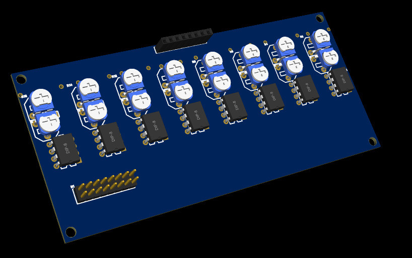
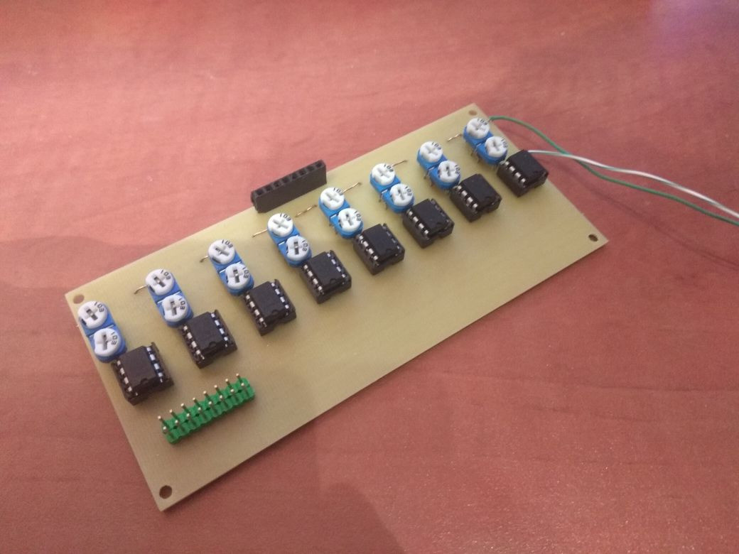
I did some experiments with the original trimpot/comparator Cybrid approach the other day.


BOM:

  • lm393 x8, 5 cents = 40 cents
  • rm065-103 (10k) x8, 7 cents = 56 cents
  • fr4 1.5mm single sided copper = 1eur give or take (expensive for what it is), machined at home

It does work, but I can now pretty confidently say that i'm not going to be using this method.
Initially I thought that adjusting some trimpots surely can't be that bad, but if you're constantly also trying out different piano key mechanics an auto callibration method is a must.


gzpiano

@RIP

RIP I thought there was still that equal-keypress-unequal-MIDI-velocity bug? Or was it purely mechanical as you showed in that video? Also, I overheard the discussion about the trimmers, but you are not doing comparators, are you? If correct, what do you need the trimmers for and what would you replace them with?

Yes - mechanical. I recently had the piano action torn down, completely rebuilt, and regulated. Made a huge difference. Next I am redoing sensor mounts with more precision.

The biggest remaining source of note-to-note variation is CNY-70 part-to-part tolerance. The trimmers were a per-sensor constant gain to to correct that CNY-70 problem, but am moving the correction into firmware. Won't need the trimmers.

(downside of firmware is, worst-case, lose a bit of ADC range … I've proved it doesn't really matter).

I'm curious if the QRE113 sensors you selected have this same issue?

In any case, this is all unrelated to the stem piano mainboard and firmware on GitHub.


RIP

gzpiano Next I am redoing sensor mounts with more precision.

Hope you can take inspiration from my setup, which is solid as a rock.

gzpiano The biggest remaining source of note-to-note variation is CNY-70 part-to-part tolerance.
gzpiano but am moving the correction into firmware.

Sounds like a good approach to me

gzpiano I'm curious if the QRE113 sensors you selected have this same issue?

Crosstalk? Yes, but less so that the CNY70. That depends purely on the geometry, namely if one sensor is able to "see" the light generated by its neighbor. I guess you could totally solve that with 87 baffles, but that's a pain to build and regulate and if they jam with the hammers can even be damage. I am satisfied with the recessed installation of my sensors in that 3D-printed protector you must have seen. Crosstalk is not 100% solved, but it's very low and potentially could be corrected in software (I don't expect it to be a problem and I am not planning to do the correction, but someone else might).

Perhaps you are thinking of sensor-to-sensor variability. I tested just a few samples, and in a precarious setup, so I can't say for sure, but it appears not. I was expecting to do more tests on the installed sensors I have on the piano, but then life happened (I switched a job) and pandemic made it much harder to find parts, so that got kicked down the road. The best data I collected is available in the data directory on github. I think I have more data saved somewhere if you want, but check what is available to see if the resolution is enough to answer your question.


DavisB

Do any of the designs use op-amps?

LM358 arrived in mail ready for some experimentation!

Very ubiquitous, very cheap (2-3 cents per LM358 dual opamp!), but only now I'm starting to familiarize myself with various technical parameters that define them:

  • Common mode voltage-range, in case of LM358, it's supply voltage(denoted by Vs) Vs - 2. If you supply it with 5V, the output range ought to be 0-3V or so.

  • Slew rate - how quickly the opamp outputs can change, 0.5V/uS, which means that to jump from 0 to 3V it would take 6 microseconds. If I understand it correctly.

LM358 are considered slow op-amps, but probably fast enough if one is used per 8 or 16 keys or so?

Are any of the designs using these or different op-amps?

What are your thoughts on using them for amplifying the sensor signals (probably in so called differential amplifier configuration)?


RIP

DavisB Are any of the designs using these or different op-amps?

Yes Jay's piano-conversion use them in transinpedance configuration. Check his wiki on github


gzpiano

Those are good op amps.

My piano has a single THS4281. Need speed for 1Msps ADC.

I just noticed you posted some questions last year. Sounds like a fun project.


DavisB

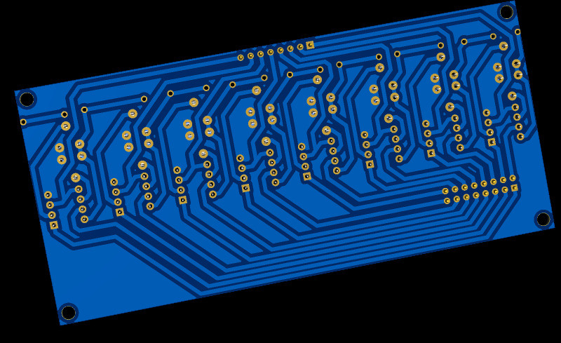
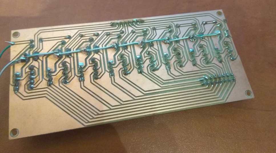
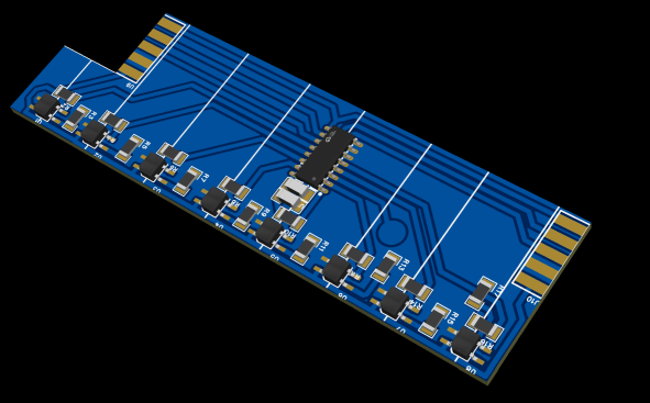
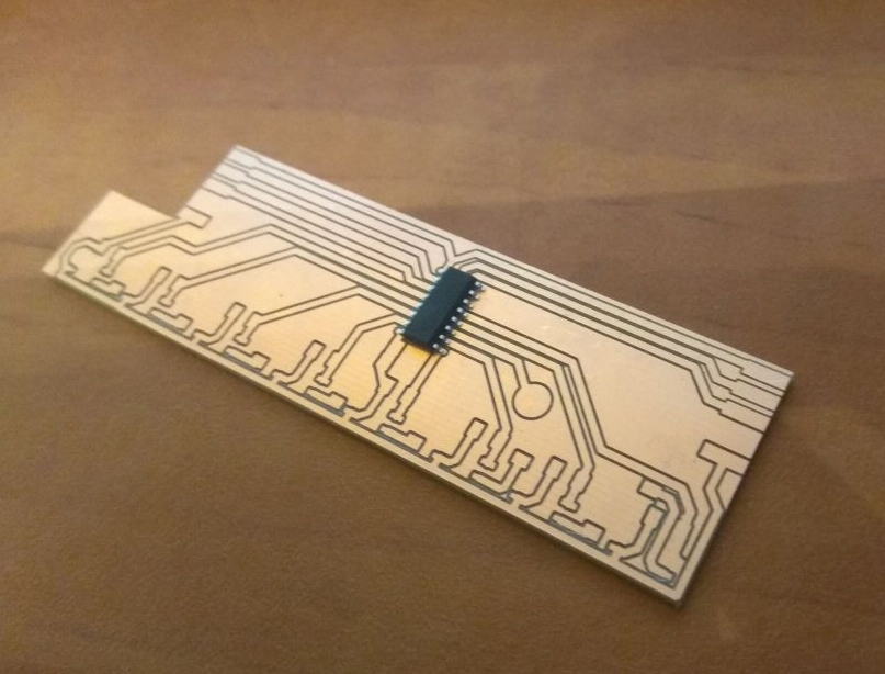
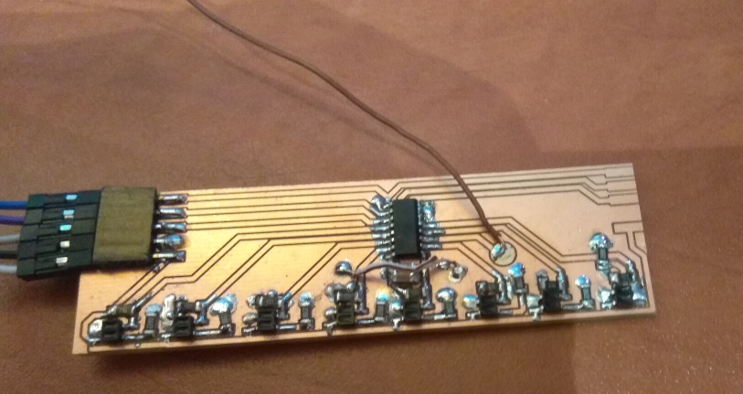
Testing CD4051 analog 8-to-1 mux with sensors placed under the keys, unequally spaced to fit right under the appropriate white/black keys.


All these machined boards look so pretty before they get gooped up by sloppy solderjob.
Design wise I like this, 3 wire address shared between 11 boards of 8 sensors, where you stick one board into another.

And then 11 analog wires go into some main board (or maybe get amplified in between?)

My second attempt to solder SMD components, and I can instantly tell that this is not the correct soldering approach, and an approach with a hotplate and gray-goopy solder probably has to be used instead.

BOM:

  • 8x iter8307 (original Everlight Electronics source), 7cents a piece = 56cents
  • CD4051, 8cent
  • 1206 MultiLayerCeramic capacitor, 10nf+100nf, 1cent
  • 1206x16 1% resistors = 3.2cent total (getting higher tolerance resistors would have almost no meaningful impact on price, so that's probably worth to order those)
  • single sided copper FR4, for the area, roughly 30cents
  • pin header on both sides would be 2.5cent

Resistors & caps don't have to be in 1206 size, but I'm inexperienced with dealing with SMD, so I wanted to start with big and easy to handle, plus, 1206 make it possible to make a "jump" on single sidded copper designs, which otherwise would require twosided copper.


DavisB

After some further experiments with putting ITR8307 under the keys, I'm noticing some considerable crosstalk between the keys (pressing keys to the left & right of the sensor impacts the readings).

I'm not 100% conviced that it won't work reasonably well even with this amount of crosstalk, because it still might...

However, I'm slowly starting to suspect that any method that involves optical sensors simply won't do because of just how close the keys for my piano are to each other.

The black key of my piano itself is only 7.5mm wide (!!!), and the width of the key above the sensor for white keys can be as narrow as 11mm. (this is 132mm octave action).

Perhaps if the ITR8307 IR LED is shone less brightly with a higher value resistor, the issue would be less pronounced, or maybe some plate could be machined that are put on top of the PCB that would block some the light coming from the sides, however those walls can only be 2mm-3mm high at best, since that's the distance to the sensor once key is pressed down...

It might be the case that I do have to use the slot-through type optical sensors in the end, since those have no issues with crosstalk at all (and avoids analog domain altogether, which is a huge win in my book), but will require to machine an slot-through key element per every piano key.

There was some other member of this forum who was making his own narrow key action (probably not as narrow as mine) and he had hall-effect sensors (which probably also have cross-talk issues?), i wonder if those are worth even trying...

RIP

DavisB I'm noticing some considerable crosstalk between the keys (pressing keys to the left & right of the sensor impacts the readings).

Define "considerable". I have not thought a lot on the key arrangement/geometry (which I use only as damper sensors, so not critical), but for hammers what happens is that most crosstalk is when the hammers are at rest: each LED shines on multiple hammers (al least 3, perhaps 5) and each sensor notices the movement of each hammer. However, nobody cares, because the important part (from which the MIDI velocity is computed) happens only when the hammer gets really close to the sensor which here acts as a virtual string. At that closeness, the hammer itself occludes the line-of-sight for both the LED and the sensor to the next hammer! That's the beauty of these small sensors compared to the CNY70! This is even more so when using the screen/protectors pictured at https://pianoclack.com/forum/d/542-update-on-piano-conversion/50 (make sure to scroll down and note that the LED/sensors are recessed inside the screen/protector). I am sure there is some residual crosstalk from light scattering all over the places inside the cabinet, but it must be pretty small. I will get to measure it when I complete at least some better ADCs than what I have now -- which hopefully will be in the next couple of months of so.

For you, my suggestion is that perhaps you can use a similar approach under the keys? I've posted the 3D-printing source file here but it's so simple that you can easily design it from scratch if you have different needs.


RIP

@SimonD @CyberGene @gzpiano @DavisB I moved this discussion here to avoid ballooning the original Cybrid thread anymore. That had the side effect of unsubscribing you, so click on the "Following" button on the top-right if you wish to resubscribe.