Skip to content

A DIY hybrid piano without ADCs (purely digital sensors)

JayKominek

DavisB Can a constant current source of this type be built from commodity jellybean components?

My design includes a simple linear constant current supply.

https://github.com/jkominek/piano-conversion/blob/master/hardware/led-power/led-power%20schematic.pdf

An op-amp capable of handling whatever the supply voltage is, a MOSFET, a resistor, and a voltage reference (which can be shared between drivers) will do. If you turn the voltage reference off to a particular op amp (driving the non-inverting input to zero) then I believe that will turn off the supply.

RIP I'm not sure the constant current driver can reliably switch on and off at that rate without 1) damaging itself in the process and 2) settling at the intended current in time for the measurement to happen.

Switching constant current drivers might not appreciate being flipped on and off like that, but simple linear ones like I include in my design can be designed such that they shouldn't have any problem. If you look at my design, that would just be a matter of flipping an op amp and a MOSFET on & off at your 8 times sample rate. The MOSFET will do that gleefully. The op amp won't mind trying, but to your second point, it might be hard to get one that can do it fast enough while satisfying all the other various requirements.

RIP The mux could be placed closed to the driven LEDs, so that meter of cable could be made 5-10cm instead which will help some, not sure if enough.

That will certainly help with the speed of things. But that length of wire without an adjacent ground is still likely to radiate.

DavisB Can this constant current source driver be made such that it's powered purely from USB?

Running something like this purely off of USB is going to make your life harder. Unless you're going to implement USB-PD, then as a practical matter that limits you to 2.5W total. Some of which you're going to lose because you're going to have to regulate that tiny trickle of 5V down to something else so that you can ensure it is stable and clean where your digital logic needs it.
DavisB

Thank you for the valuable feedback. It really got me thinking.

While the LED switching itself can be very fast, one reason this method might not work as well as I would have liked is that the phototransistors are quite slow.

ITR8307 (and CNY70 and similar) have bandwidth of around 20-40kHz depending on the load usually the 10k resistor as seen in the sample circuits) Rising/falling edge of around 20 microseconds.

If I understand correctly, when switching from one phototransistor to another (1 out of 8) up to 20microseconds are potentially necessary for the phototransistor output to settle on the correct output before even initiating any measurement or ADC conversion. This is getting too close to 10kHz-20kHz per sensor sample rate I'd like to achieve.

The difference between a photodiode and phototransistor is that phototransistor in itself functions as an amplifier of sorts, while a photodiode absolutely needs an amplifier as it outputs very little current (the transimpedence amplifier is often used in this case). Photodiodes can be very fast however (as used in fiber optics, etc)

hc238/hc138 ICs have falling rising edges of around 10ns at 5v (depends on VCC, significantly more at 3.3v).

As a rule of thumb, bandwidth of a squarewave signal is calculated using:
Bandwidth_in_GHZ = 0.35/Rise_time_in_nanoseconds.
In case of 10ns rising edge that would be ~ 35mHz.
The traces and the load will have a certain amount of capacitance and resistance - that will function as a low pass filter to reduce the 10ns rising edge to a degree.


DavisB

I'm listening to lectures by Dan Gelbart, and from my understanding, as far as high accuracy sensing is concerned -
any measurement which can be converted to time measurement can be measured to a much higher degree of accuracy.
Most things - with great care - can be measured to about 1 part per million. 1micron to 1meter, 1volt to 1microvolt, 1mg to 1kg, except time, time can be measured to orders of magnitude higher accuracy (think atomic clocks). Comparitively 1s to 1microsecond(1Mhz) is very easy and cheap to measure. Any bargain bin MCU will do.

For signals that are AC and you're measuring frequency, that becomes a measurement of zero crossing time (ie. time measurement).

This is why FM has way better noise immunity than AM, it only cares about zero crossing time (not noise on amplitude and other distortions of the signal)!

If signal is AM modulated (data is in the amplitude not carrier frequency), you can get rid of lot of the noise by building a band pass filter around the carrier frequency F.

If you amplify DC signals you get DC drift, every amplifier has an offset voltage which drifts.
DC drift is a problem if you work with low level signals in mV. AC doesn't have this problem.

Optical sensors, the ones we use, typically have peak wavelength of 940 nm. They have a built in optical band pass filter
(colored glass/colored material which filters for that wavelength).
But there are other sources of 940nm ambient light other than the IR-LED itself (room lights, outdoor lights, etc)
Working with AC also provides a way to filter out other sources if IR-LED is shone modulated with certain frequency F (10kHz-100kHz).
Then we can bandpass filter modulated frequency, thus eliminating other sources of ambient light that operate at different frequencies.

If you have an analog sensor, you want to put amplifier right next to it (if you put it on the other end, you will amplify noise, etc).

Distance sensing can be used to measure many parameters, some of them:

  1. Force (deflection of a cantilever spring, F=kX, if we can sense X we can sense F)
  2. Acceleration (deflection of a cantilever, F=mA, mass is known, F can be measured from (1))
  3. Mass (deflection of a cantilever, F=mg)
  4. Pressure (deflection of flexible diaphragm)

Many accelometer IC have silicon micro etched springs that measure distance capacitively.

For highly accurate measurements ideally you want differential sensor that eliminate drift in other parameters of the sensor.


DavisB

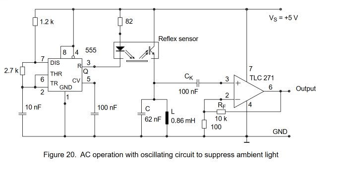
Vishay Semiconductors have "Application of Optical Reflex Sensors TCRT1000, TCRT5000, CNY70"
That has the following circuit that demonstrates use of such AM modulated signal:

The circuit in figure 20 is a simple example for operating the reflex sensors with chopped light. It uses a pulse generator constructed with a timer IC. This pulse generator operates with the pulse duty factor of approximately 1. The frequency is set to approximately 22 kHz. On the receiver side, a conventional LC resonance circuit (fo = 22 kHz) filters
the fundamental wave out of the received pulses and delievers it to an operational amplifier via the capacitor, Ck . The LC resonance circuit simultaneously represents the photo transistor’s load resistance. For direct current, the photo transistor’s load resistance is very low- in this case approximately 0.4, which means that the photo transistor is practically shorted for dc ambient light.


DavisB

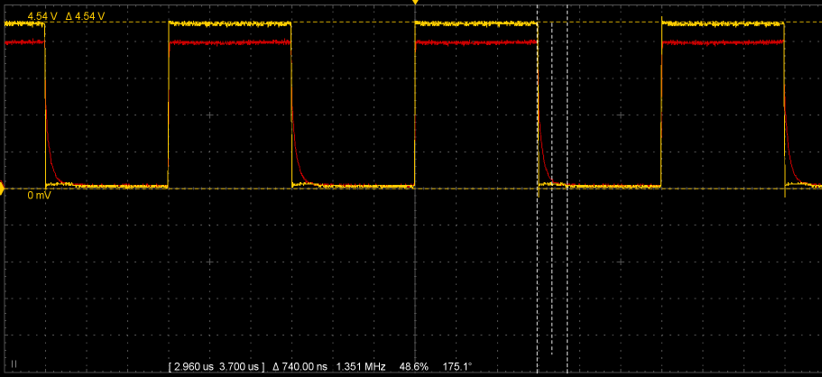
I did some measurements for Everlight elec ITR20001 phototransistor feeding into it a 160kHz 5v pwm signal from an arduino mega:

I'm getting around 800ns fall time of photo transistor output. Which is way less than specified 20microsecond rise/fall time, am I missing something?
This is using 8kOhm resistor as load on emitter side (hooked up as seen in the initial schematic, but without the hc238).

If all sensors are sampled at 20kHz, that gives 50microseconds to switch between the 8, giving 6.25us per sensor time window, 1us of which would be taken up by the transition.

Another way to look at is - if 50us are the time window to sample all 88 sensors, then 8x11 mux using 238 would eat up 8us of that budget in transitions. So this approach might as well work if that is taken into account.


DavisB

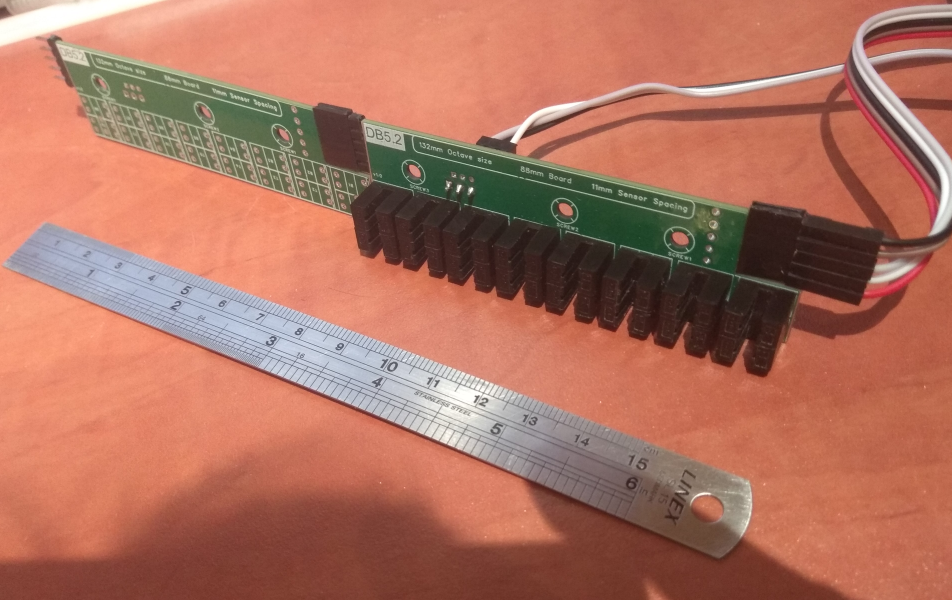
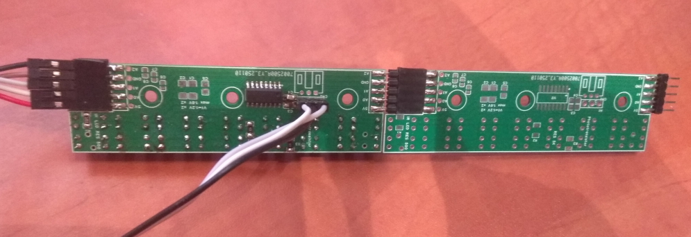
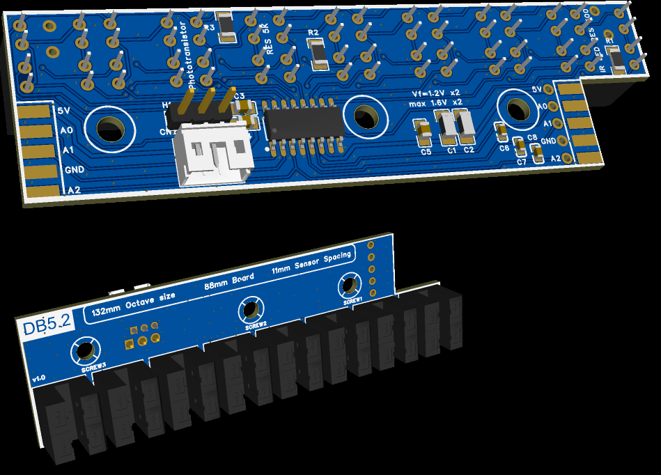
I've upgraded slot-through slit-sensor PCB design with hc238 muxing too.
Now it effectively draw less than 200mA, which means it can easily be directly powered from USB alone.
And requires only 3 resistors instead of 32 previously, only one hc238 IC per 8keys (instead of two shift registers per 8keys), 1 decoupling cap. This reduces part count and simplifies assembly (matters alot if hand placed).

A single Raspberry Pi Pico is wholly sufficient as main USB-MIDI device too, with tinyusb library. RP2040 is 70cents @ 100qty, compatible QPSI flash around 25cents. Ready made original Raspberry Pico boards are 4.2-5€, WeActStudio rp2040 is 3-4€, YD-RP2040 modules go for as low as 1.5-2.5€ a piece.

Total effective electronics BOM of this slot through design ends up being roughly 50-60€, including PCBs, but excluding assembly. No external power supplies necessary either. This is as simple as it gets, but it does require a mechanical element to move through the slit, the only downside of this approach.

I suspect a wholly analog version can also be built in roughly same electronics BOM budget, but it is highly dependent on built in ADCs of stm32 mcus to be "good enough".

My first experiences with programming stm32 via SWD has been thoroughly positive, debugger and breakpoints work great, while also being able to see peripheral registers and their state as machine is running. This is great for troubleshooting. (not using cubeIDE)

stm32 has two vendor specific APIs, stm32 HAL (high level) and stm32 LL (low level). STM32 LL are just thin wrapper over peripheral registers that are memory mapped into flat address space. Interfacing with peripherals is essentially taking 32bit addresses (as pointers) and reading/writing to values to them. Reference manuals have descriptions in detail where each peripheral is in memory space. I find stm32 LL API particularly pleasant and easy to understand.

Other than vendor specific peripherals, both rp2040, stm32g431, stm32h7, teensy4.1, they all have arm cortex m0/m4/m7 cores . RP2040 is a cortex m0 (no floating point unit), teensy4.1 and stm32h7 are cortex m7 (have floating point units), just clocked at 600mhz(teensy) vs 480mhz (stm32h750). They are programmed and debugged in the same way via SWD/JTAG.

I have weact stm32g431 (2x 12bit 0.25us adcs) devboard on hand with weact stlink probe. DMA DAC works well (very useful as signal generator!), sending ADC readings via UART using DMA works well too. ADC conversions thus far seem to work great via DMA too (ADC conversions automatically get written in buffers).

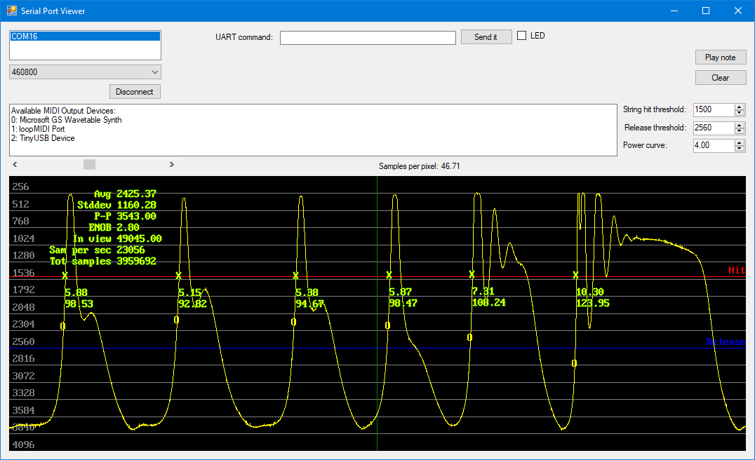
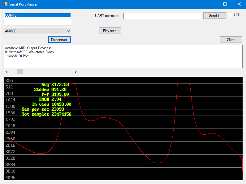
I wrote a small app for streaming and displaying ADC values over UART, works easily up to 1mbit baud rate (haven't tested higher)

(ignore ENOB readings, those are rough estimates if the signal is not "moving")

This is capable of also generating MIDI signals to be routed to Piano VIs. Which means that I can develop and test velocity calculation algorithms fully on PC before porting it over to a MCU.

The "tricky part" is setting up the peripherals/timers/DMA and buffers such that almost nothing is blocking (or calling interrupts as interupts also take cycles to switch in and out of).

For h7 480mhz / 88keys * 20khz sampling = 272 cpu cycles per key. This is only slightly less than teensy at 340 cpu cyles per key.


scherbakov.​al

DavisB ….. 480mhz (stm32h750)

There are stm32h723vgt6 boards with 550mhz processor and built-in full color display for only 10 dollars. I myself switched from stm32h750 to stm32h723. They work great and are inexpensive.


scherbakov.​al


RIP

Great to hear that the STM32 are working for you (in fact they are working fantastically well for me too -- but at work where we have a team of specialized engineers each of which can take care of one small but essential aspect of the design and where I never touch them directly).

For a hobbyist like me, almost-alone in this project, the STM32 was putting myself squarely in the "project does not get completed" camp. Like this guy puts it better than I can.

https://www.youtube.com/watch?v=4jgTCayWlwc


DavisB

Got tinyUSB MIDI working on stm32g4 as well!

Now that I've gotten tinyusb MIDI work with both RP2040 and STM32G4, i'm pretty confident that I'll be able to get it working for any of the supported MCUs on the list.
https://github.com/hathach/tinyusb/blob/master/docs/reference/supported.rst

Of which rp2040 and stm32h750 offer the best value! Honorable mention WCH CH32V203C8T6, RISCV 144mhz, LQFP-48(7x7), 50cents a piece - great MCU for basic MIDI devices with sliders and knobs, etc!

Now I can send MIDI directly from MCU via USB, or send sensor data via UART and generate MIDI on PC via virtual MIDI port!

The first algorithm for analog velocity calculation is very simple - store last N samples, and once current sample crosses some threshold, take current sample and one sample N samples ago (N = 32, 64 or 128, ....) and then take the average of that. This doesn't even require floating point numbers, or division and can be implemented in few cycles with just fixed point math, etc. Then I feel that calculated velocity has to be fitted onto some curve before being translated into MIDI.

(taking current sample and one sample N samples ago is eerily similar to effectively reducing sample rate by N)

Perhaps there's some smart things that can be done with those samples (filtering, rejecting obviously noisy samples, etc), but nothing pops up at the moment! Any ideas?


RIP

DavisB Got tinyUSB MIDI working on stm32g4 as well!

Did you got it working on its own, were you able to integrate it with another project (e.g. the ADC example, or your own fully fledged algorithm)? In my experience the former is quite easy, the hard part is the latter. If that is what you have done, big kudos to you!

DavisB Any ideas?

Plenty. Most of the discussion on this topic happened in the thread linked below (and links therein), but many of my multi-part "Build your own DIY hybrid piano - step xxx" have some. And to be clear most of those are not mine, the contributions are from the whole community here!

https://pianoclack.com/forum/d/289-scanning-speed-and-velocity-mapping-of-cybrid


DavisB

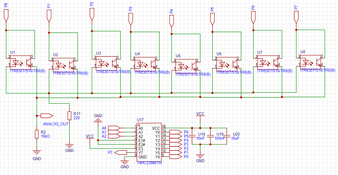
I've built the circuit as seen in this image:

And it doesn't work works only to extremely slow switching speeds, ie. switching only couple of hundred of times a second. After that it works, but only allows to sense one-sensor at a time (at speeds switching sensors 160khz times a second) - if any of the sensors is active, it just reports low 0V for all the other sensors, regardless of their state.

And It's not obvious why is it so... and seems like the only way it could happen is if the transistor starts conducing in reverse for some time after being switched off? (hc238 can both source and sink current).

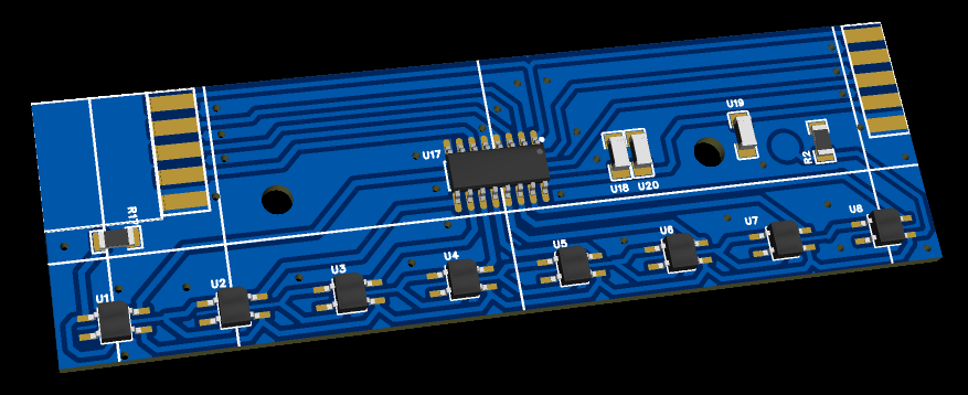
PCB looks like this, double sided.


scherbakov.​al

Hello! I'm not sure, but it seems to me that the problem may be that the transistor in the sensor takes about 20us to open and close. 20us = 50 kHz period. As stated in the datasheet: Oh yes, it was mentioned above..

I am very impressed that you managed to run the tinyusb library on the stm32! I once tried to make this library work, but apparently I didn't spend enough time studying it and it didn't work out. Nevertheless, it would be extremely interesting to look at the stm32 project with tinyusb running.


CyberGene

scherbakov.​al sorry, I misread your post, never mind 😃(edited my comment)


scherbakov.​al

A couple of years ago, a friend proposed a sensor circuit that used ambient light filtering. It's a cool scheme, I couldn't have come up with such a thing. The LED would turn off, the transistor would be measured, and then the LED would light up. The value of the previous measurement would be subtracted from the current measurement on the transistor. This process seemed to work well, but we ran into a problem when we tried to adjust the frequency of the sensor's stable operation. The frequency was about max 10 kHz when we used CNY70 components.

https://github.com/brrastak/midi_sensor/blob/main/midi_sensor.pdf

I do not know how it works) There's also a need for a control driver for such a sensor.

CyberGene sorry Nothing) I've got a double post above (2 weeks ago. I was writing from the subway and lost contact for a moment).. I tried to delete it, but I couldn't find how. It can be deleted


DavisB

The odd thing is that the sensors work just fine easily switching up to 20khz as long as they are alone, and don't share the same time-multiplexed analog output signal line at the same time. (or when they operate at very slow switching speeds, then the circuit works as intended)

I've also measured response time of these phototransistors via an oscilloscope individually, which makes me think there's some weird interaction between the sensors themselves as they are switching between each other while sharing the same output line.

The only solution to this issue that I can imagine is putting a signal switching diode on each transistor output...


scherbakov.​al

Alternatively, you can try connecting the outputs from the sensors to another such multiplexer, which would be controlled by the same channels and demultiplexed the outputs into one. It's just that the specifications for the diodes indicate the response time: one is about 200 ns, the other is 50ns, the ultrafast diode is 35ns, and this multiplexer works faster than 20ns.


DavisB

I did a small prototype on a breadboard switching 3 sensors with arduino nano (arduino nano pins can source and sink up to 20mA)

PORTD |= (1 << PD3);  
PORTD &= ~(1 << PD4); 
PORTD &= ~(1 << PD5); 
delayMicroseconds(6); 
  
PORTD &= ~(1 << PD3); 
PORTD |= (1 << PD4);  
PORTD &= ~(1 << PD5); 
delayMicroseconds(6);

Using essentially the same circuit (but without 238), and shared analog output wire, and it works without any issues.

Now I'm starting to suspect that I have a bad solderjoint somewhere (or one of the 8 sensors is shorted or misbehaving) or some issue of that type, or else it doesn't make sense that this works and the 238 version doesn't. It has to be some sort of silly mistake somewhere.


DavisB

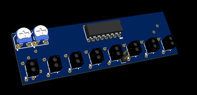
I've made a hc238 muxing circuit using just through-hole components for purely testing purposes since it easy to attach oscilloscope and see if solder joints are OK. And this time it works as intended!

(trims are there for testing purposes only so i dont have to resolder resistors)

However there are still issues with sensors impacting each others readings. For example if one sensor is reflecting, you get max value 4096, and if all sensors are reflecting, you get only around 3500 as max value, or sensors next to each other. Which isn't optical crosstalk as far as I can tell!

So this kind of muxing probably works just fine as-is for slit sensors, but for purely analog sensors it needs some improvements (such as only blinking leds via hc238 to reduce power consumption and still use analog mux for constantly powered phototransistors?)

The good news is that I've made all the software side on stm32 take zero CPU cycles to do ADC conversions and muxing.
PWM timer with 160khz frequency, 1.25us low (for the transition), 5us high - all easily adjustable.

Every 6.25us timer triggers DMA transfer a bitpattern on relevant GPIO pins (memory to peripheral DMA transfer to BSRR - Bit Set Reset Register)
On the rising edge of 5us high initiates automatic ADC conversion (after the 1.25us transition settling time)
ADC conversion automatically outputs results via another DMA channel out into a result buffer and moves to the next position in a circular buffer.

This uses no interrupts, and effectively no cpu cycles!

You get automatically filled buffers with sensor positions all the time with zero CPU involvement! Sampled at the exact muxing timings I specify!
This happens fully automatically in the background all the time.

What's beautiful about this is that it has the exactly same code and hardware pinouts when muxing using analog switch cd4051 or muxing using hc238!
I took my old PCB that uses analog switches plugged it in - and it just works! Same code & same hardware interface!
All 8 sensors beautifully streamed via UART (up to 5.7ksps each via 921kbit uart)!

Might be a good idea to add another ping-pong DMA buffer (like double buffering)...?! software side really is the easy part with debugger where you can add memory and variable watches and see buffers, periperals and their data changing in real time!

Another cool feature of stm32g4 is VREFBUF (with available values for VREF being 2V, 2.5V, 2.9V). This also works wonderfully.
Built in OPAMP follower also seems to work great. (havented tested built in programmable gain opamp yet!)

If muxing/adc sampling can be made like this to take zero cycles, it feels almost as if single measly stm32g431 (arm32 cortex m4 @ 170mhz) might just be fully sufficient for a full piano...?


DavisB


Pcbs from JLCPCB came for the hc238 muxed slit version. Seems to work as expected at 20khz per sensor at the moment!
Components per board - 2*8sensors (very fast and easy to solder!), 3resistors(1206), 2 decoupling caps (100nf, 1uf 0805), one sop-16 ic, lots of DNP (do not place) pads, 1.2mm fr4 2layer, one side almost unbroken ground plane (except for where the pcbs join).

Beginner hand-solder friendly (except for two 0805 caps?), the only upgrades to this design that I can think of are:

  1. Make it into 2pcbs (11mm * 44keys * 2pcbs=484mm * 2pcbs) instead of 11pcbs (of 11mm * 8keys * 11pcbs=88mm * 11pcbs)
  2. Smaller slit sensors, with smaller slit (these have massive 1mm slit where the IR light shines through).


(soldermask is incorrect, it is powered from 3.3v!

Very cost effective design, ~ 4eur (2eur boards, 2eur shipping), for 5pcbs (out of 11 total). Needs one more main board (<100x100mm) with rp2040 and that's it.


« Previous Page Next Page »