Skip to content

Cybrid - a DIY MIDI controller with grand piano action

AlexanderBunt

RIP Okey, this sounds good. If it is possible to do two measure points without potentiometers, that would be better of course. I didn't know this was possible, so thanks for the advice!

I think that is what I will do then. Use one sensor per key, and adjust the measure points in code. I see you did this with a Raspberry Pi, but do you think it's also possible with for example a Teensy 3.5 of Arduino Mega (calculating speed etc.)?


CyberGene

What is the travel of a key in mm? From the pictures it seems it might have a long travel which means you can put the measurement points farther apart which in turn would make the need to have very quick measurement less important compared to a piano. In the Cybrid I have put both points within the last 1mm of the hammer travel (to allow for off-the-jack detection) and the hammer itself has a very high velocity (5 times greater than that of the key) and so I completely eliminated an ADC approach and relied instead on the trimpots because the entire solution provides a pretty quick measurement of those high velocities and that is also possible through just a single controller like the Teensy. I have not been following what Jay and Del Vento use in their projects since I moved on from this project to other things (it was rather a one-off project to make myself busy for a while and learn new things but I’m not actively interested in the Cybrid or the other similar projects anymore), however to my understanding their projects rely on multiple ADC-s that will solve the inherent problems of Cybrid: having to regulate all the 88 * 3 trimpots, as well as having to scan very quickly in order to measure precise durations. With on-site ADC-s you can measure each hammer velocity (or rather position) in isolation, without having to wait for the entire scan to finish, and also having absolute positions of hammers at frequent sample intervals allows for eliminating trimpots and instead using software to calibrate stuff and to model velocity detection, prediction, etc. All that being said, the complete calibration took me 2 hours and I didn’t have to touch it too often. Maybe touch a trimpot or two once a week. But what Del Vento and Jay are using is much more advanced.

Besides, they are still working on their projects and everything is fresh in their heads. As I said, I moved on to just learning new Scriabin pieces on the piano, so I don’t remember a lot in details about the Cybrid 😃 Also I waste a lot of time screwing around with sound synthesis on virtual analog synths and stuff like that these days…


AlexanderBunt

CyberGene The travel from full up to full down is around 80mm (8cm), but it depends on the console. But, the measurement distance should be not more then 1cm maximum (so first point at 10mm from the botton of the shaft and second point at the bottom of the shaft (ca. 0mm)), because many times the carillonneur keeps the key down while pressing it more times after eachother. But I don't know anything about the technic with the sensors at all, so I don't know what is the best (and most easy) solution. For example, I don't know what you guys mean with 'ADC'…

CyberGene With on-site ADC-s you can measure each hammer velocity (or rather position) in isolation

This seems to be a nice solution, but I don't know a thing about ADC's and measurement speeds. So is this still possible with a measurement range of max 10mm (I think maybe even less, at about 5mm…). And I don't know what's the best way to programm this kind of software… Maybe somebody can help me with that too.

I'm sorry if I sound a bit dumb on this forum, but I have no real experience with this stuff ;-) So I don't know what will work good that isn't too difficult.

From my perspective, it would be best to have one CNY70 sensor per key, at the bottom of the shaft. Then let the Teensy or Arduino calculate all the velocity's based on the time between the first and second point. But as I said, no knowledge about this, so I don't know what's possible.


CyberGene

A single Teensy has 25 analog pin inputs. Well, internally there are only 2 ADC-s, so they will be multiplexed as far as I remember but it doesn't hurt for you to test if you can directly wire multiple CNY70 to the analog inputs and try reading them in sequence. If that works quick enough, then you can use 2 Teensy boards for 50 keys (or three Teensy boards x 18 inputs each = 54 analog inputs) and then just record MIDI in your DAW from multiple MIDI inputs which is certainly possible on a Mac. If that works (because 10mm is a lot and would allow for the slight imprecision introduced through the slow sequential and multiplexed ADC), then your task is just wiring 52 CNY70-s and 52 resistors and you will be good to go.

P.S. My very first POC was using an Arduino with a single CNY70 and a resistor hooked to the analog input:

It wasn't MIDI-ed, just printing duration:

boolean firstActivated = false;
boolean secondActivated = false;

long firstActivatedAt;

void setup() {
  Serial.begin(9600);
}

void loop() {
  int v = analogRead(A0);
  float volts = (v / 1024.0) * 5.0;
  long timestamp = micros();
  
  if (volts >= 4.0) {
    if (!secondActivated) {
      secondActivated = true;
      long duration = timestamp - firstActivatedAt;
      Serial.println(duration);
    }
  } else if (volts >= 2.0) {
    if (!firstActivated) {
      firstActivated = true;
      firstActivatedAt = timestamp;
      Serial.print("*");
    }
  } else {
    secondActivated = false;
    firstActivated = false;
  }


  //Serial.print("Value: ");
  //Serial.print(v);
  //Serial.print(" Volts: ");
  //Serial.println(volts);
  
  //delay(1);
}


CyberGene

Thinking about this in retrospective, I based my entire Cybrid implementation (trimpots and comparators) on the assumption ADC is slow but I never actually measured how slow it is. In that ADC link from the forum I posted above, it seems the precision of the ADC depends on the duration of sampling but it is possible to sample the ADC on every ADCK which might be very short. I am wondering if just measuring the CNY70-s directly through the Teensy ADC, even with a low precision, might have actually be the better way to implement the Cybrid 🤣 Imagine if the effective result is not unlike what I achieved through the entire contraption that the trimpots, comparators and transceivers do 🤣 Anyway, back to Scriabin I guess...


AlexanderBunt

CyberGene 10mm is a lot

Less would be better or worse?


AlexanderBunt

CyberGene Imagine if the effective result is not unlike what I achieved through the entire contraption that the trimpots, comparators and transceivers do

Haha that would be nice to find it out just now😂


CyberGene

AlexanderBunt I think 10mm is within the range of the CNY70, although I'm not sure what its range is but intuitively I'd avoid measuring longer distances than 10-20mm.

But I mean something else. In order for a velocity detection only at hammers for a piano to work correctly and not miss strikes, one needs to measure only the last 1-2mm of the hammer strike. Because it's possible for you to press the key until it reaches the escapement point and then throw it. The escapement distance is 1-2mm of the hammer. However the key-hammer leverage is 1:5 meaning the hammer travels 5mm for every 1mm of key travel. This means the hammer is very fast and if you have to measure only 1mm of its travel, you have to be very quick.

Now, if that distance was 10mm, you have more tolerance to measure the start and end. And then, since you will be measuring Carillon keys which are not leveraged, they will be much slower than a piano hammer.

Which is why I think you have much less critical requirement for a Carillion project compared to a piano. And is why I think even direct ADC from the CNY70 multiplexed from all its analog pins might turn out to work for you. Then everything will be in the code.


RIP

AlexanderBunt I think that is what I will do then. Use one sensor per key, and adjust the measure points in code. I see you did this with a Raspberry Pi, but do you think it's also possible with for example a Teensy 3.5 of Arduino Mega (calculating speed etc.)?

I am using a Raspberry Pi pico (last part is very important), which is the wimpiest thing you can think of (well I guess the C=64 I used in my youth was wimpier 🤣 and much larger). If I can do it with that (and I can), you can do it with anything.The only question is if that "anything" has enough ADC inputs

AlexanderBunt This seems to be a nice solution, but I don't know a thing about ADC's and measurement speeds.

ADC = Analog to Digital Converter. A thing that takes a voltage input, such as the one produced by these CNY70 or similar sensors and transform it into a digital number. See https://pianoclack.com/forum/d/289-scanning-speed-and-velocity-mapping-of-cybrid/121 for the latest example of what the data looks like.

Resolution is measured in number of bits, which usually is 10, 12 or more. However the ENOB, Effective Number of Bits, is lower, because there is "noise" (=imperfection) in the measures and the lowest digits cannot be trusted. You see it very well on the pictures linked above. For the pico, the resolution is 12 bits, but the ENOB is slightly less than 9. The measurement speed is frequency and is measured in thousands of "samples" (measurements) per second. Depending on how fast the thing you want to measure moves, you need to "sample" it faster. Surprisingly, the wimpy pico is one of the fastest sampler, at 500kSample/s (so fast that it has trouble putting that information somewhere, because it is too slow to move so much data -- but it can measure it and compare it to threshold)

Also, since ADCs are relatively expensive, they are often "multiplexed" i.e. one ADC serves multiple "channels" which in our case would be attached to a different sensor for each key. So as CG said you can use just a couple of those boards to sense all the keys you need.

AlexanderBunt CyberGene 10mm is a lot

Less would be better or worse?

Less would make it harder in that you have to sample quicker. No better or worse per se, just have to be faster, which reduces the number of ADCs and multiplexers you can use.

I recommend that you read the the READMEs and wiki of @JayKominek 's repository at https://github.com/jkominek/piano-conversion which is really great with lots (and probably "all you need to know") of info. What might be missing there are only "obvious" things which "everybody knows", i.e. that you can find easily on wikipedia and/or online tutorials at Sparkfun, DigiKey, personal blogs etc.

Nice to have you onboard!


AlexanderBunt

RIP Nice to have you onboard!

For me it is very nice that you guys are so nice and that you waht to help as much as you can! I can't say enough thank you for that…

I will answer more tomorrow. It's just so nice to have this forum here. I think I couldn't do this without your help, @RIP, @CyberGene and @JayKominek


AlexanderBunt

CyberGene

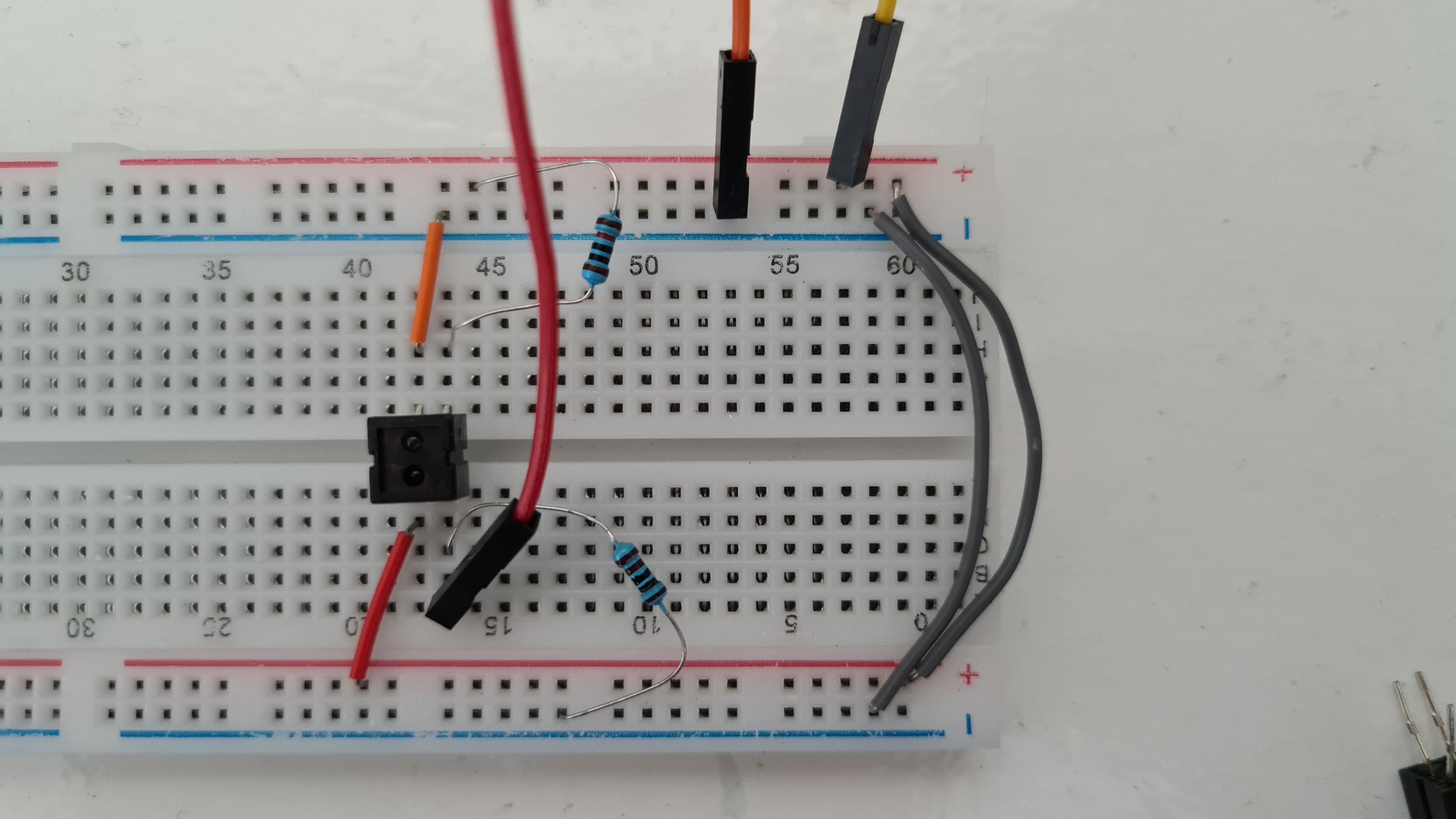
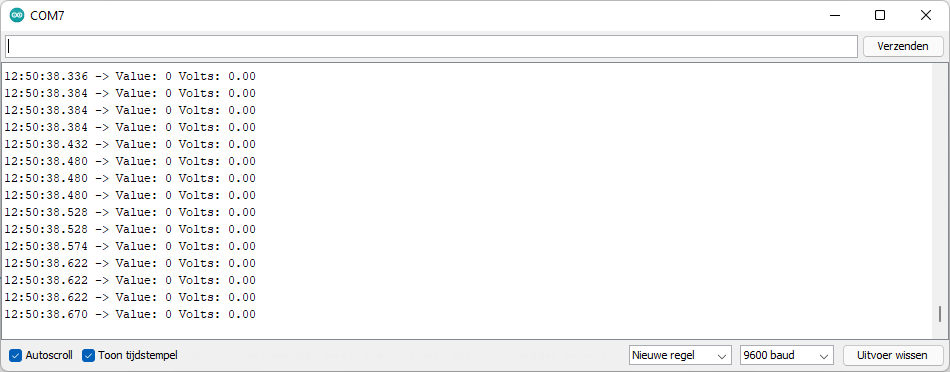
I tried wiring it up like you did, but sadly, I don't get any result at all…

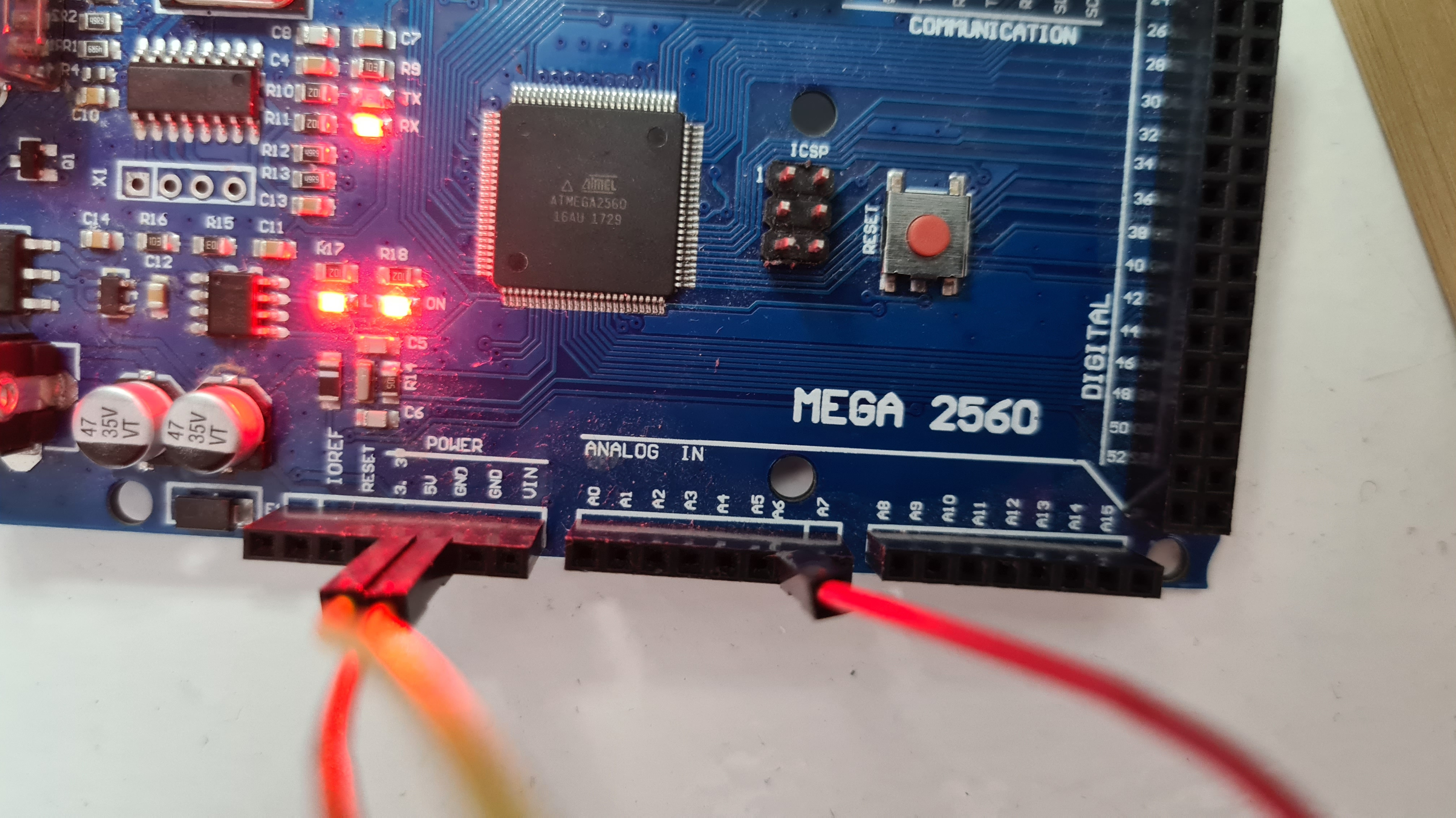
Here is what I have:

Result is this:

I have already tried different sensors and also different arduino's, but they all give the same result.

When I deattach the resistor going from bottom left of the sensor to the ground, I get decent values around 1024, but then the sensor doesn't react to movements at all.

However, when I attatch different kinds of resistors, I get better data I see now. What kind of resistors do I need?


AlexanderBunt

Getting there slowly, but I've got a few questions:

  1. Which resistors do I need to get the right values?
  2. How to do it with just 3.3V on the Teensy? (Now trying it on the 5V of the arduino…)
  3. I now get some usable values, but the last 1cm is not working fine (value stays a bit the same or is even going lower). I think it's because of the wrong resistors, but I don't know…

@CyberGene… maybe you can help me with this?


HZPiano

Hello,

@AlexanderBunt , from forensic evidence ("Toon tijdstempel") I deduct that you are either Dutch or Flemish?

☺️

Cheers and happy experiments,

HZ


AlexanderBunt

HZPiano Haha well spotted… I'm Dutch😇


AlexanderBunt

gzpiano Ah thanks! I think this will help me.


CyberGene

AlexanderBunt Which resistors do I need to get the right values?

You have to provide 20mA of current to the LED part of the CNY70. So, you use the Ohm's law to calculate the resistor value depending on the voltage:

I = U / R
R = U / I = 5V / 20mA = 5 / 0.02 = 250 Ohm

Or for 3.3V power, R = 3.3 / 0.02 = 165 Ohm.

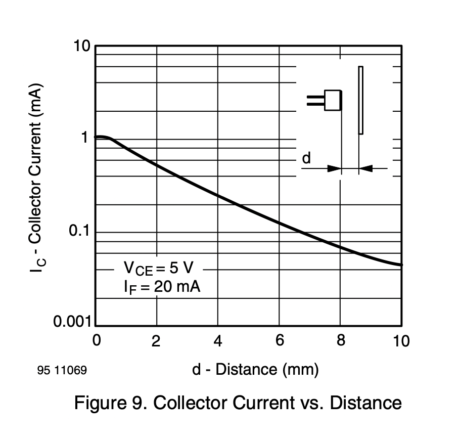
The other resistor, the one that connects the phototransistor emitter to the ground, in my case was 4.7k. The phototransistor will change the current that passes from its collector to the emitter based on the proximity of objects. It means the transistor acts as a resistor between its collector and emitter. So, if you connect one more resistor after its emitter, you will effectively implement the so called voltage divider (two resistors connected in series and the middle point dividing the voltage that is applied on the top resistor).

Now, here's the part the shows the collector current, depending on the distance:

When the object is as close as possible, the highest current is 1mA. So, if it were directly connected to the ground and the voltage was 5V, it would mean the transistor acts as R = U / I = 5V / 0.001A = 5000 Ohm = 5k

When the object is at a higher distance, the effective resistance increases (because the current drops).

Now, the max current of 1mA should be able to pass through the second resistor too, which means it should have a resistance that is less or equal than the effective resistance of the transistor, so it should <= 5k, which is why I used a 4.7k. You can use any value you want but the voltage drop in the measurement point (between the two resistors) would drop too much if the second resistor has a very low value. So you choose one that is comparable to the first one, hence 4.7k which is a good enough value.

If you will be powering through 3.3V, just recalculate, it's easy, the effective resistance is 3.3k, so the second resistor should be probably 3k.

I might be wrong about all that though, electricity has never been a favorite subject of mine 😃


RIP

AlexanderBunt I now get some usable values, but the last 1cm is not working fine (value stays a bit the same or is even going lower). I think it's because of the wrong resistors, but I don't know…

Everything that others say is right, but let me add that you might be experiencing a characteristic of the sensor for which your only solution might be switching to a different one. The data sheet that @CyberGene posted show the "flattening" at the last 0.5mm from the sensor, but in real life testing (which I haven't posted yet, but I will post it eventually here) I have experienced it happening at much longer distance. @JayKominek has experiencing it too at around 5mm, as shown at https://pianoclack.com/forum/d/289-scanning-speed-and-velocity-mapping-of-cybrid/116 -- so if your "10mm" is eyeballing the distance while moving one hand and looking the screen, what you are seeing is consistent with what everybody else is seening.

This is a unavoidable characteristics of the design of these sensors, due to the parallax of the LED and phototransistor being separate by a distance. The CNY70 have that separation large, so it's more affected than the QRE1113 and EAITRCA6 which have the distance much smaller. But even these are affected by the same problem, just at much closer distances. See here for the raw data on the 'CA6 sensor (and python script to analyze it) and/or https://pianoclack.com/forum/d/289-scanning-speed-and-velocity-mapping-of-cybrid/122 for a plot and discussion: as you can see most peaks do have a "hole". It's not the hammer bouncing back-and-forth, it's the sensor reducing its output at very close distances. We have to design the software and/or the mechanics (e.g. a stop to prevent hammers going too close to the sensors) to live with it.

If you look in @JayKominek github repo you'll find these mechanical "stops" which I plan to use (scaled down in dimensions) for the smaller sensors I will use. @JayKominek since we are discussion this, I actually have concerns that the "holes" in your things will be too big for the size of the hammers and that it will eventually cause too much wear on the hammer sides. Moreover it looks to me that it'd make alignment more critical. Have you thought about all these issues? BTW, should we make a separate thread for this subject?


AlexanderBunt

RIP I made a new thread called 'Hybrid Carillon in the making'…


« Previous Page Next Page »